Information processing apparatus, information processing method, program, and storage medium

Active Publication Date: 2011-09-08
CANON KK
View PDF11 Cites 40 Cited by
  • Summary
  • Abstract
  • Description
  • Claims
  • Application Information

AI Technical Summary

Benefits of technology

[0011]In view of the above-described problems, the present invention provides a

Problems solved by technology

Thus, there is a problem that the relationship between the images obtained by different modalities cannot be easily recognized.
However, it may be difficult to satisfy the assumption that the subject is a rigid body depending on the part of the subject to be examined.
For example, in the case where a mammary area is

Method used


Image

  • Information processing apparatus, information processing method, program, and storage medium
  • Information processing apparatus, information processing method, program, and storage medium
  • Information processing apparatus, information processing method, program, and storage medium

Examples


Example

First Embodiment

[0026]An image processing apparatus according to the present embodiment has a function of acquiring both an MRI image of a subject which is captured in advance and an ultrasonic tomographic image of the subject which is being obtained by an operator (an engineer or a doctor) in an interactive manner, generating an MRI tomographic image which corresponds to the ultrasonic tomographic image, and displaying the generated MRI tomographic image.

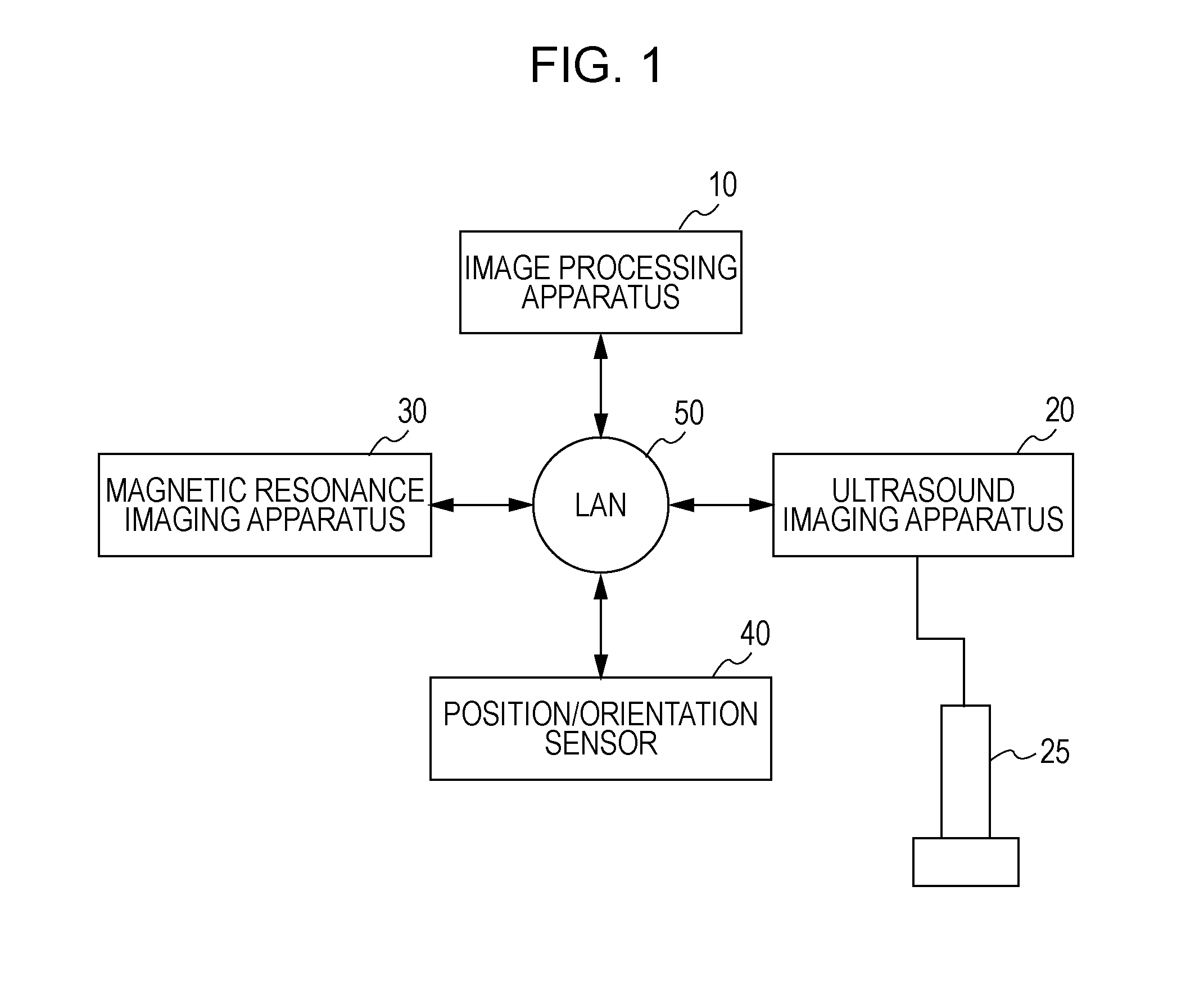
[0027]FIG. 1 is a diagram illustrating the structure of apparatuses connected to an image processing apparatus 10 according to the present embodiment. As shown in FIG. 1, the image processing apparatus 10 is connected to an ultrasound imaging apparatus 20, a magnetic resonance imaging apparatus 30, and a position / orientation sensor 40. These apparatuses are connected to each other via a local area network (LAN) 50 of Ethernet (trademark) or the like. The connection method is not limited to this, and the apparatuses may also be conn...

Example

Second Embodiment

[0091]An image processing apparatus according to the present embodiment provides a function of acquiring both an MRI image of a subject and a three-dimensional ultrasonic image of the subject and displaying the images such that the images are positioned with respect to each other.

[0092]The image processing apparatus according to the present embodiment includes a second elasticity-information acquiring unit that differs from that of the first embodiment. In the first embodiment, a tissue structure is estimated from the MRI image, and the elasticity information of the MRI image is estimated from the statistics. In contrast, in the present embodiment, the elasticity information of the subject in the MRI image is estimated using MRI images obtained while the subject is in different postures. In this case, the elasticity information based on the actual deformation of the subject can be obtained. Therefore, the accuracy of the elasticity information can be increased.

[0093...

Example

Third Embodiment

[0122]An image processing apparatus according to the present embodiment has a function of acquiring both an MRI image of a subject which is captured in advance and an ultrasonic tomographic image of the subject which is being obtained by an operator (an engineer or a doctor) in an interactive manner, generating an MRI tomographic image which corresponds to the ultrasonic tomographic image, and displaying the generated MRI tomographic image.

[0123]The structure of apparatuses connected to an image processing apparatus 800 according to the present embodiment is similar to that shown in FIG. 1. Similar to the image processing apparatus 10 according to the first embodiment, the image processing apparatus 800 is connected to the ultrasound imaging apparatus 20, a magnetic resonance imaging apparatus 30, and a position / orientation sensor 40 via a LAN 50. These apparatuses are similar to those described in the first embodiment, and explanations thereof are thus omitted.
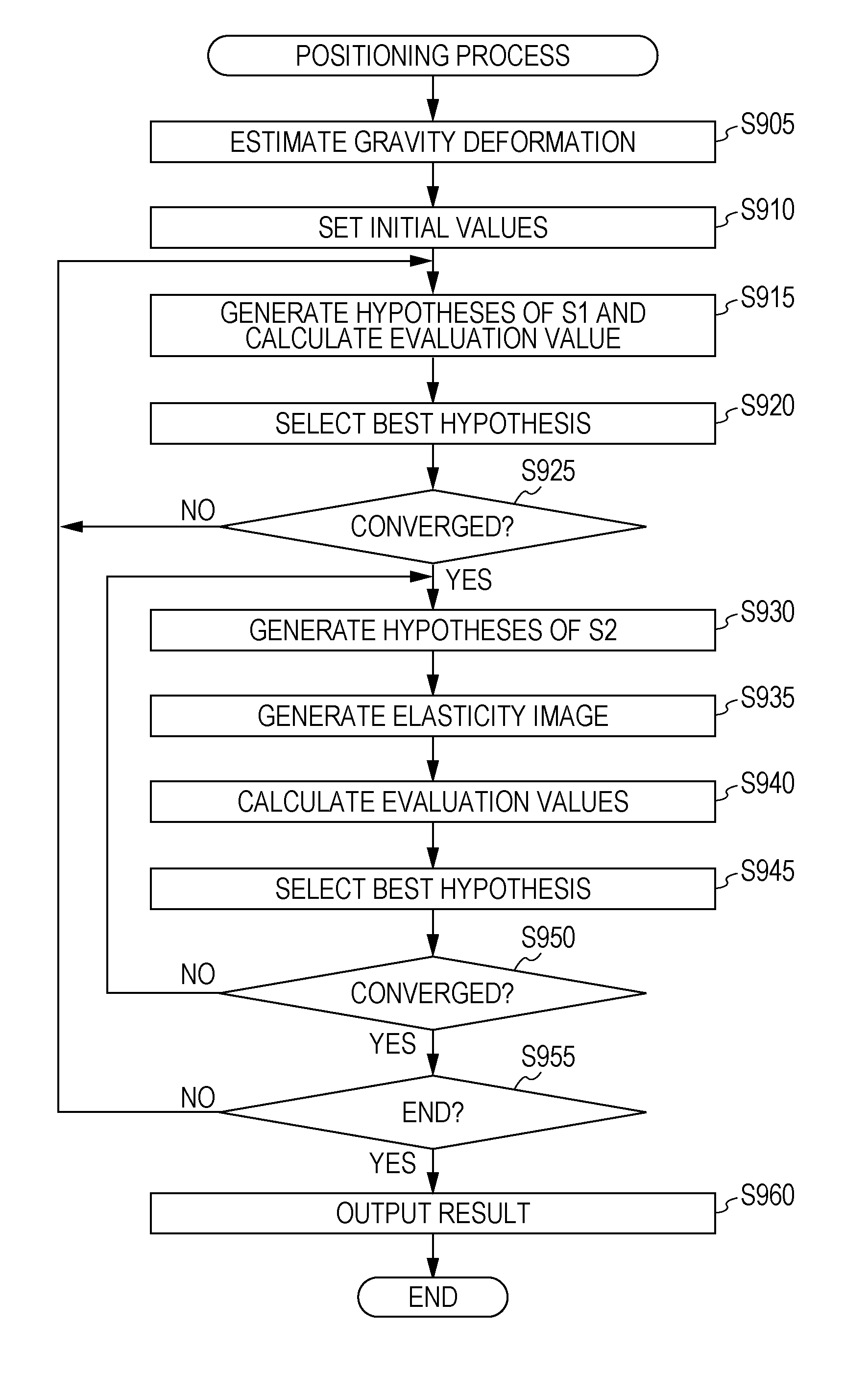
[0124...


PUM


Abstract

First elasticity information regarding elasticity of a subject in a first image and second elasticity information regarding the elasticity of the subject in a second image are acquired, and the first image and the second image are positioned with respect to each other on the basis of at least one of the first elasticity information and the second elasticity information.

Description

TECHNICAL FIELD[0001]The present invention relates to a technique for positioning images captured by a plurality of image capturing apparatuses, and more particularly, to an image processing technique using elasticity information of a subject.BACKGROUND ART[0002]In the medical field, doctors display medical images of subjects on a monitor and interpret the displayed medical images to observe the statuses or changes over time of lesions. Apparatuses (modalities) for capturing this type of medical image include an X-ray computed tomography (X-ray CT) apparatus, a magnetic resonance imaging (MRI) apparatus, a nuclear medicine diagnosis apparatus (single-photon-emission computed tomography (SPECT) apparatus and positron emission tomography (PET) apparatus), and an ultrasound imaging (US) apparatus. Each of the above-mentioned modalities is capable of providing an image of internal tissues of a subject by measuring a physical quantity specific to the modality. Images obtained by differen...

Claims


Application Information

Patent Timeline
IPC IPC(8): G06K9/00
CPCA61B5/055G06T7/0028G06T2207/30004G06T2207/10132G06T2207/10088G06T7/33A61B6/5247A61B6/032A61B6/037A61B6/5223A61B8/14A61B8/4254A61B8/483A61B8/485A61B8/5261A61B8/08G06T1/00
Inventor SATOH, KIYOHIDEENDO, TAKAAKIISHIKAWA, RYO
Owner CANON KK
Why Eureka
Try Eureka