Suction motor housing for an upright surface cleaning apparatus

a technology for cleaning apparatuses and suction motors, which is applied in the direction of motor fan assembly mounting, cleaning filter means, suction filters, etc., can solve the problems of increasing reducing and reducing the portability of upright vacuum cleaners for the elderly or the infirm, so as to reduce the size of suction motor housings and reduce the portability of upright vacuum cleaners. , the effect of increasing the weigh

Inactive Publication Date: 2011-09-15
G B D
View PDF14 Cites 26 Cited by
  • Summary
  • Abstract
  • Description
  • Claims
  • Application Information

AI Technical Summary

Benefits of technology

[0005]According to one aspect, an upright surface cleaning apparatus is provided with a suction motor housing that includes a post motor filter chamber. The post motor filter chamber is positioned spaced from but facing the suction motor. The air accordingly will travel from the air treatment member or members to the suction motor inlet. The air will travel through the fan of the suction motor and then by or through the motor section to cool the motor. The air will then travel laterally, and possibly upwardly and laterally, to the post motor filter. This constructions permits a reduction in the size of the suction motor housing.
[0006]Traditionally, upright surface cleaning apparatus have had large, bulky frames or upper housings. The upper housing has a recess for removably receiving a cyclone. The housing has also incorporated air flow passages (e.g., from a dirty air inlet to a cyclone inlet and from a cyclone outlet to a suction motor inlet). This structure increases the weight of an upright vacuum cleaner and also reduces the portability of an upright vacuum cleaner for the elderly or the infirm. A reduction in the size of the suction motor housing reduces the weight and increases the portability of the surface cleaning apparatus.
[0007]In a preferred embodiment, the suction motor is mounted on the upright section of the vacuum cleaner (e.g., the portion that comprises the push handle) and is spaced from the floor cleaning head. Such a construction is advantageous as it permits the floor cleaning head to extend further under furniture (e.g., floor cleaning head may be passed under furniture until the bottom of the upright section contact the furniture). However, if the components of the vacuum cleaner (e.g., the motor and the cyclone housing) are too high on the handle, then the hand weight of the vacuum cleaner during operation will increase thereby decreasing the usability of the vacuum cleaner. Reducing the height of the suction motor housing permits the suction motor to be provided on the handle, thereby reducing the height of the floor cleaning head and increasing the ability of the floor cleaning head to clean under furniture. At the same time, the components on the vacuum cleaner may be mounted lower thereby reducing hand weight.

Problems solved by technology

Traditionally, upright surface cleaning apparatus have had large, bulky frames or upper housings.
This structure increases the weight of an upright vacuum cleaner and also reduces the portability of an upright vacuum cleaner for the elderly or the infirm.
However, if the components of the vacuum cleaner (e.g., the motor and the cyclone housing) are too high on the handle, then the hand weight of the vacuum cleaner during operation will increase thereby decreasing the usability of the vacuum cleaner.

Method used


Image

  • Suction motor housing for an upright surface cleaning apparatus
  • Suction motor housing for an upright surface cleaning apparatus
  • Suction motor housing for an upright surface cleaning apparatus

Examples


Embodiment Construction

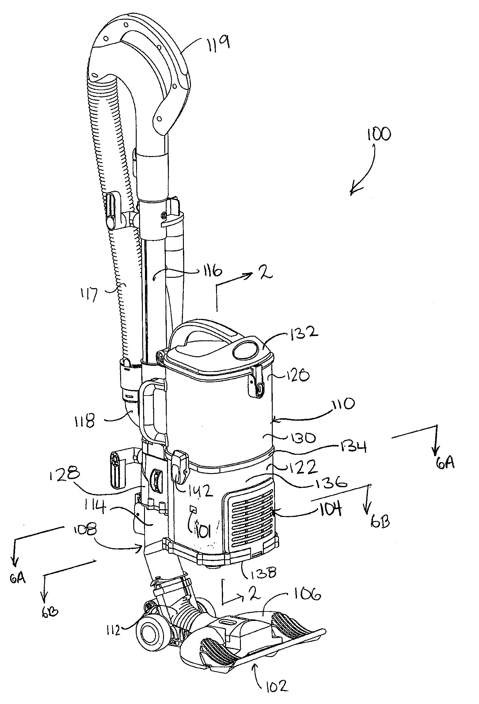
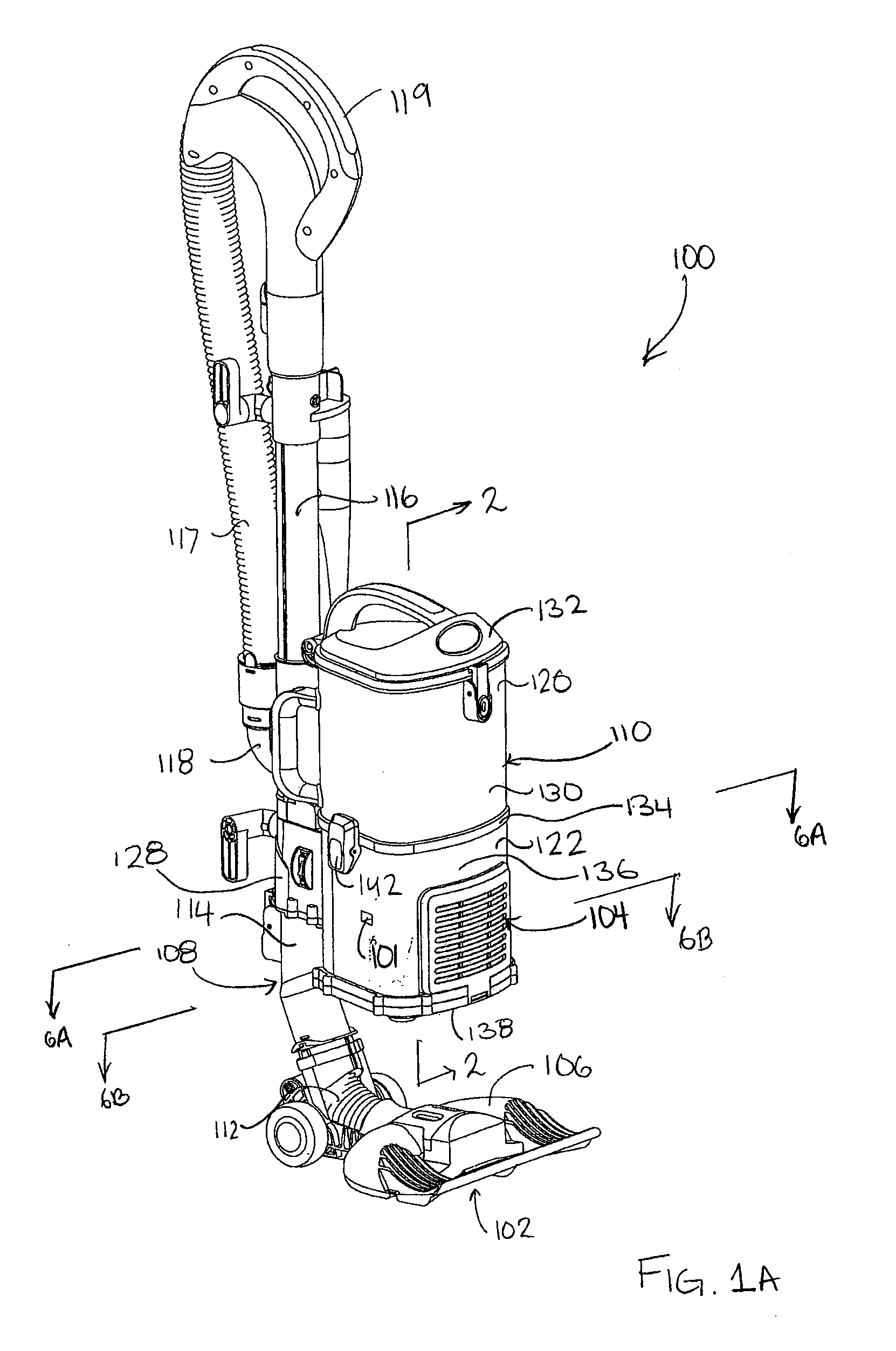
[0027]Referring to FIG. 1a, a first embodiment of a surface cleaning apparatus 100 is shown. In the embodiment shown, the surface cleaning apparatus 100 is an upright surface cleaning apparatus (otherwise referred to as an upright vacuum cleaner). In alternate embodiments, the surface cleaning apparatus may be another suitable type of surface cleaning apparatus, such as a canister type vacuum cleaner, and hand vacuum cleaner, a stick vac, a wet-dry type vacuum cleaner or an carpet extractor.

[0028]Referring still to FIG. 1a, the surface cleaning apparatus 100 has a dirty air inlet 102, a clean air outlet 104, and an air flow passage extending therebetween. In the embodiment shown, the dirty air inlet 102 is provided in a floor cleaning head 106. From the dirty air inlet 102, the airflow passage extends through the floor cleaning head 106, and through an air conduit 108, to an upright section 110. The clean air outlet 104 is provided in the upright section 110. In the embodiment shown...


PUM


Abstract

An upright surface cleaning apparatus comprises a floor cleaning head having a dirty air inlet, and an air flow passage extending from the dirty air inlet to a clean air outlet. An upright section is moveably mounted to the surface cleaning head between a storage position and an in use position. The upright section comprises a filtration member and a suction motor provided in the air flow passage. The suction motor has an air inlet end, an opposed distal end, and an air inlet direction. The upright section further comprises a motor housing. The motor housing comprises a motor section in which the suction motor is provided. The motor section has a first end at the air inlet end of the suction motor and an opposed second end at the distal end of the suction motor. An openable post motor filter chamber is provided in the motor housing and has an inlet end and an outlet end. At least a portion of the filter chamber is provided in the motor section. The inlet end includes a finger guard and the filter chamber has a direction of airflow that is transverse to the air inlet direction of the suction motor. A post motor HEPA filter is removably mounted in the filter chamber.

Description

FIELD[0001]The disclosure relates to surface cleaning apparatuses, such as vacuum cleaners. Particularly, the disclosure relates to upright surface cleaning apparatuses.INTRODUCTION[0002]The following is not an admission that anything discussed below is prior art or part of the common general knowledge of persons skilled in the art.[0003]Various constructions for surface cleaning apparatus such as vacuum cleaners are known. Currently, many surface cleaning apparatus are constructed using at least one cyclonic cleaning stage. The air is drawn into the vacuum cleaner through a dirty air inlet and conveyed to a cyclone inlet. The rotation of the air in the cyclone results in some of the particulate matter in the airflow stream being disentrained from the airflow stream. This material is then collected in a dirt collection chamber, which may be at the bottom of the cyclone or in a dirt collection chamber exterior to the cyclone chamber (see for example WO2009 / 026709 and U.S. Pat. No. 5,...

Claims


Application Information

Patent Timeline
Patent Type & Authority Applications(United States)
IPC IPC(8): A47L9/16A47L9/10
CPCA47L5/28A47L9/122A47L9/22A47L9/1691A47L9/1683
Inventor CONRAD, WAYNE ERNEST
Owner G B D
Why Eureka
Try Eureka