Power supply device for sinker electric discharge machining

a technology of power supply device and sinker, which is applied in the direction of power supply circuit, electric circuit, manufacturing tools, etc., can solve the problems of reducing responsiveness, damage to switching elements, and the inability of specialized current pulses with a long on time to realize a low wear rate, so as to improve the removal rate of materials

Active Publication Date: 2011-09-15
SODICK CO LTD
View PDF16 Cites 8 Cited by
  • Summary
  • Abstract
  • Description
  • Claims
  • Application Information

AI Technical Summary

Benefits of technology

[0019]According to the present invention, switching elements are turned on and off in response to gap current in order to keep peak current constant, which means that there is no need for an electric discharge machining circuit to include a current limiting resistor. Also, both of the first and second switching elements are on from a first time (t1) when electric discharge is generated across the machining gap until a second time (t2) when gap current reaches the peak current. As a result current pulses having a steep rising edge are supplied to the machining gap.
[0020]At the second time (t2) only one of the first and second switching elements is turned off, and at a third time (t3) when a specified time period (ty) elapses during the ON time (Ton) from the second time (t2), both of the first and second switching elements are on. From the second time (t2) until the third time (t3), due to an inductance component remaining in the electric discharge machining circuit, the gap current flows in a closed circuit that includes the machin

Problems solved by technology

Heat generated by this high speed on/off switching operation reduces the responsiveness of the switching elements, and might also damage the switching elements.
In such a case, a specialized current pulse having a long ON time can not realize a low wear rate.
If the voltage of the DC power

Method used


Image

  • Power supply device for sinker electric discharge machining
  • Power supply device for sinker electric discharge machining
  • Power supply device for sinker electric discharge machining

Examples


Embodiment Construction

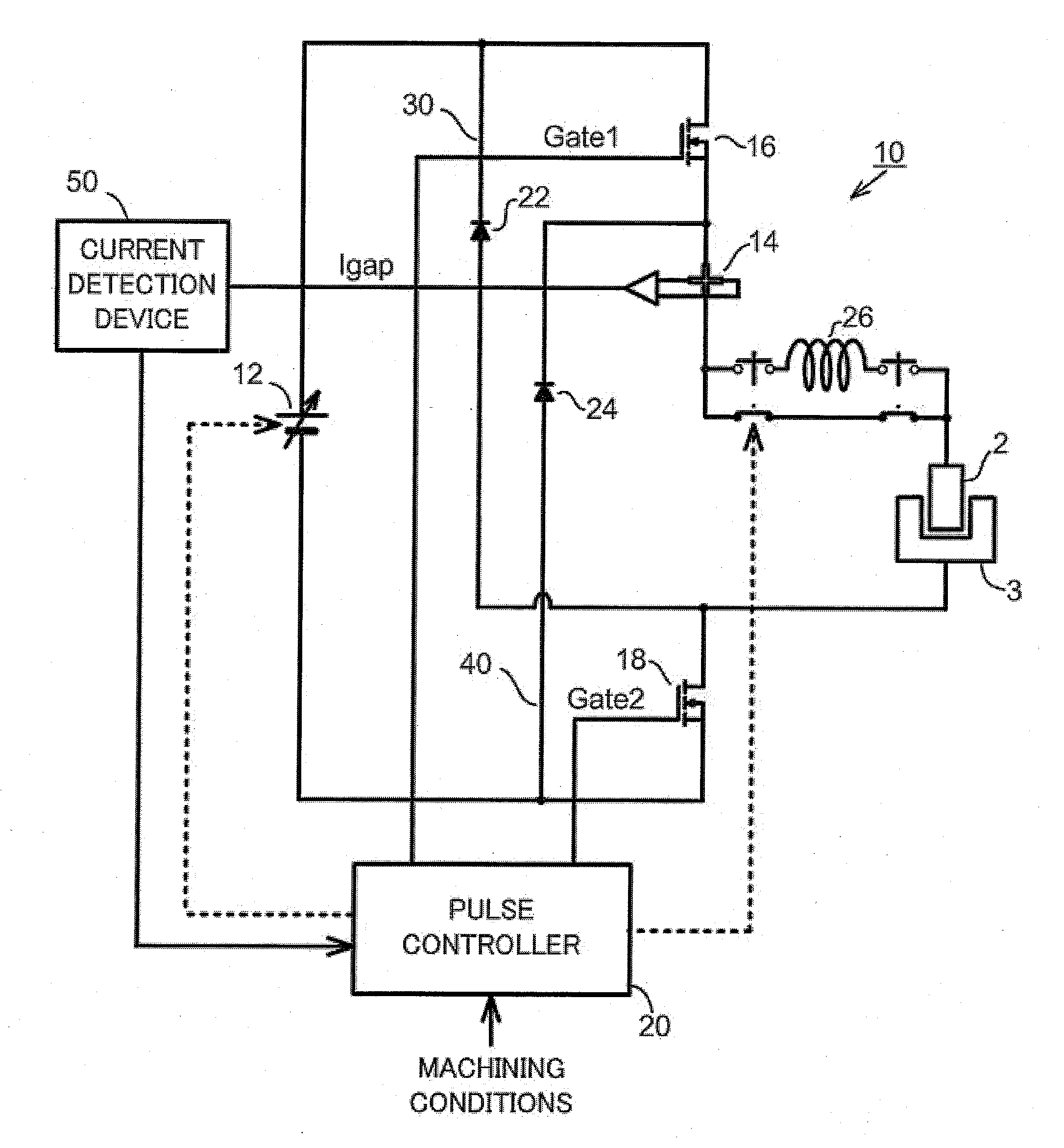
[0024]A first embodiment of a power supply device for sinker electric discharge machining of the present invention will be described with reference to FIG. 1. The power supply device for sinker electric discharge machining comprises an electric discharge machining circuit 10, a pulse controller 20, and a current detection device 50. The electric discharge machining circuit 10, includes a machining gap formed between a tool electrode 2 and a workpiece 3. The electric discharge machining circuit 10, comprises a DC power supply 12, a current sensor 14, a first switching element 16 and a second switching element 18. A current limiting resistor is not included in the electric discharge machining circuit 10, and resistance is minimized. A positive pole of the DC power supply 12 is connected to the tool electrode 2, while a negative pole of the DC power supply 12 is connected to the workpiece 3.

[0025]The current sensor 14 is provided at a position in the vicinity of the machining gap, for ...


PUM

PropertyMeasurementUnit
Timeaaaaaaaaaa
Currentaaaaaaaaaa

Abstract

A power supply device comprises a DC power supply (12), a current sensor (14) for detecting gap current (Igap) flowing through the machining gap, a first switching element (16) connected in series between the DC power supply and the tool electrode (2), a first reverse current prevention diode (22) connected in parallel with the DC power supply and connected in series with the first switching element (16), a second switching element (18) connected in series between the DC power supply and the workpiece (3), a second reverse current prevention diode (24) connected in parallel with the DC power supply and connected in series with the second switching element (18), and a pulse controller (20) for controlling the first and second switching elements in response to gap current (Igap). From a first time (t1) when electric discharge is generated across the machining gap, until a second time (t2) when the gap current reaches the peak current during the ON time, both of the first and second switching elements are on. At the second time (t2) only one of the first and second switching elements is turned off.

Description

BACKGROUND OF THE INVENTION[0001]1. Field of the Invention[0002]The present invention relates to a sinker electric discharge machining device for forming a required cavity, recess or hole, etc. in a workpiece by intermittently causing electrical discharge in a machining gap formed between a tool electrode and a conductive workpiece. In particular, the present invention relates to a power supply device for sinker electric discharge machining, for supplying a sequence of controlled current pulses to the machining gap.[0003]2. Description of the Related Art[0004]Generally, with a sinker electric discharge machining apparatus, a metallic workpiece is located in a tank, and a machining gap is filled with dielectric fluid. If a power supply applies a voltage to the machining gap, the dielectric fluid is ionized. Then, electric discharge is generated across the machining gap and an ON time (alternatively called duration time) starts. During the ON time, discharge current flows through the ...

Claims


Application Information

Patent Timeline
IPC IPC(8): B23H1/02
CPCB23H1/022B23H2600/12B23H2300/20
Inventor YAMADA, KUNIHARUYANAGISAWA, TOMOYUKI
Owner SODICK CO LTD
Why Eureka
Try Eureka