Convertible discharge system for bale shredder

a discharge system and shredder technology, applied in grain milling, agriculture tools and machines, solid separation, etc., can solve the problem of not giving the opportunity to closely control the size and placement of the windrow

Active Publication Date: 2011-09-15
DURATECH INDS INT
View PDF18 Cites 8 Cited by
  • Summary
  • Abstract
  • Description
  • Claims
  • Application Information

AI Technical Summary

Benefits of technology

[0008]Either the side conveyor or the fan can be operated as the bale shredder is moved along the ground, so that windrows of material can be formed. In the case of using the fan the material can be blown with a good volume of air to provide a layer of bedding or a covering layer on the ground for other purposes. The conversion from a fan discharge to a side conveyor discharge is very simple, utilizing suitable fasteners for removing and replacing the desired blocking panel, and selectively driving either the side conveyor or the fan.

Problems solved by technology

Material also can be blown into feed bunks, windrows or stockpiles for later use as well, but the fan tends to spread the material and blow away smaller particles, and does not give the opportunity to closely control the size and placement of the windrow.

Method used


Image

  • Convertible discharge system for bale shredder
  • Convertible discharge system for bale shredder
  • Convertible discharge system for bale shredder

Examples


Embodiment Construction

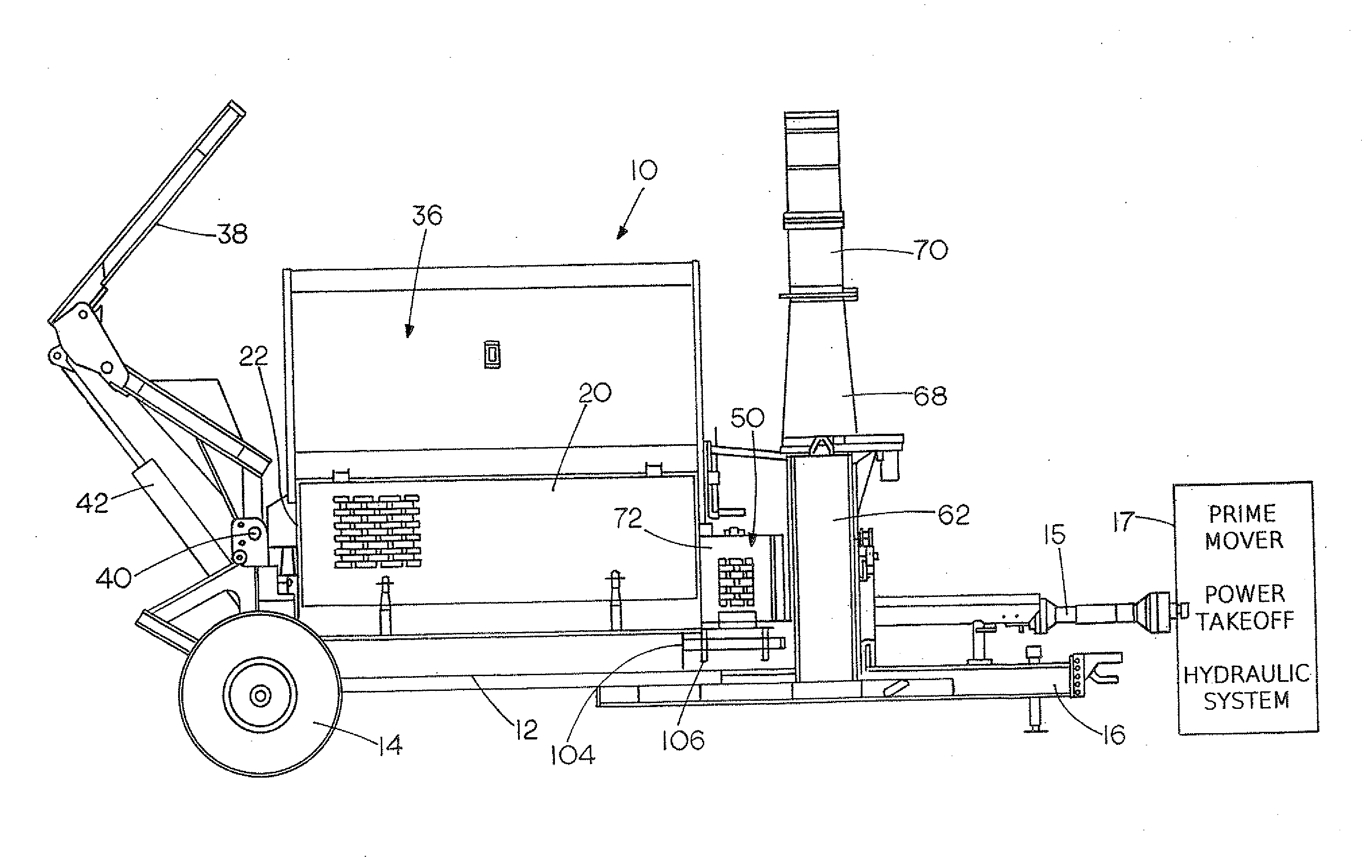
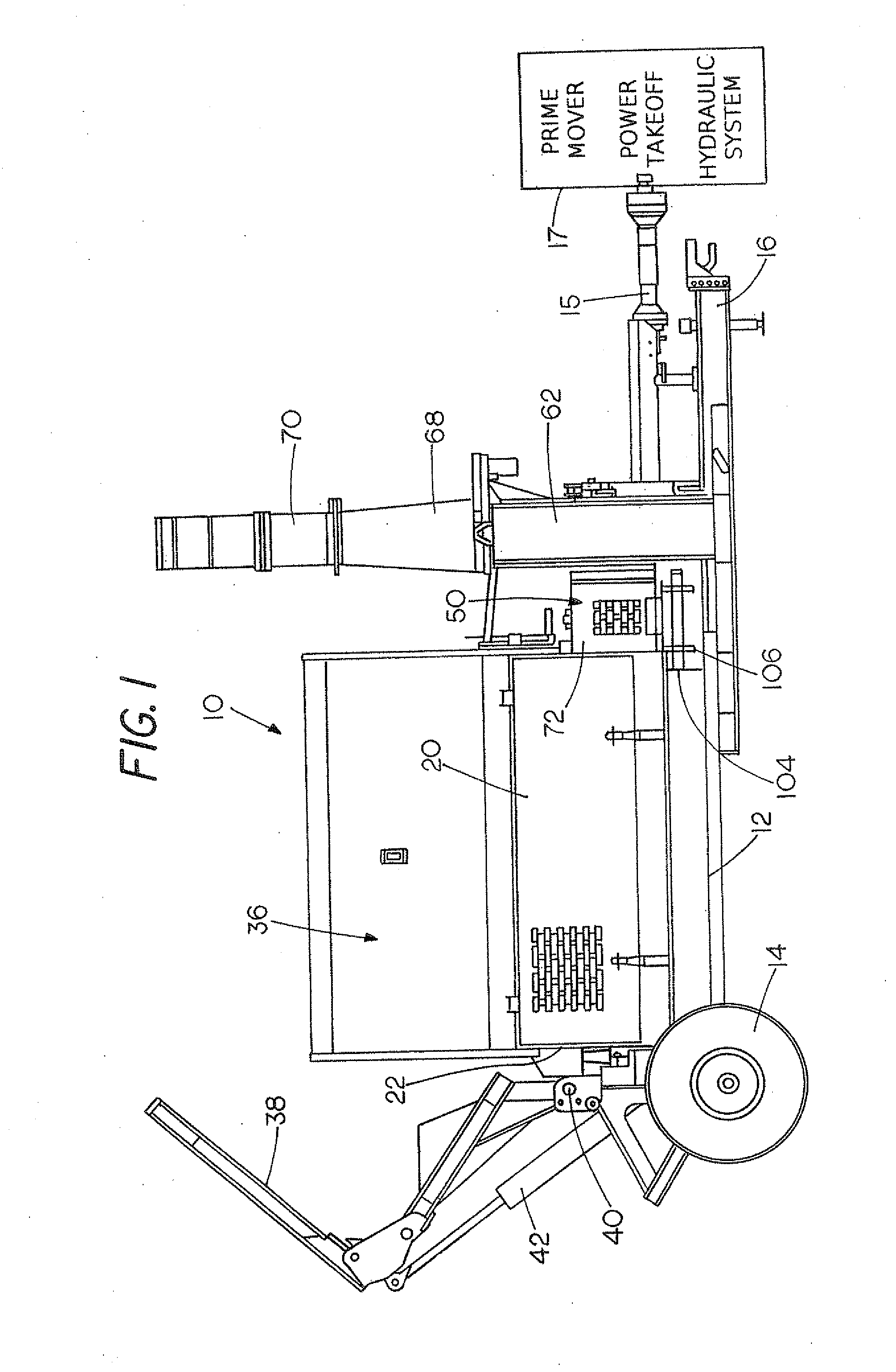
[0018]A bale shredder indicated generally at 10 includes a frame member 12 that has rear wheels 14 and a suitable towing arrangement including a forwardly extending tongue 16 that is designed to be attached to a tractor or other prime mover represented schematically at 17. The prime mover 17 includes a power take off and a hydraulic system including a pump, reservoir and valve system. A power takeoff shaft 15 is driven by the prime mover used for powering the bale shredder from the power take off of the tractor or other prime mover 17, as is well known in the art. The tractor or prime mover also provides hydraulic power for components as desired.

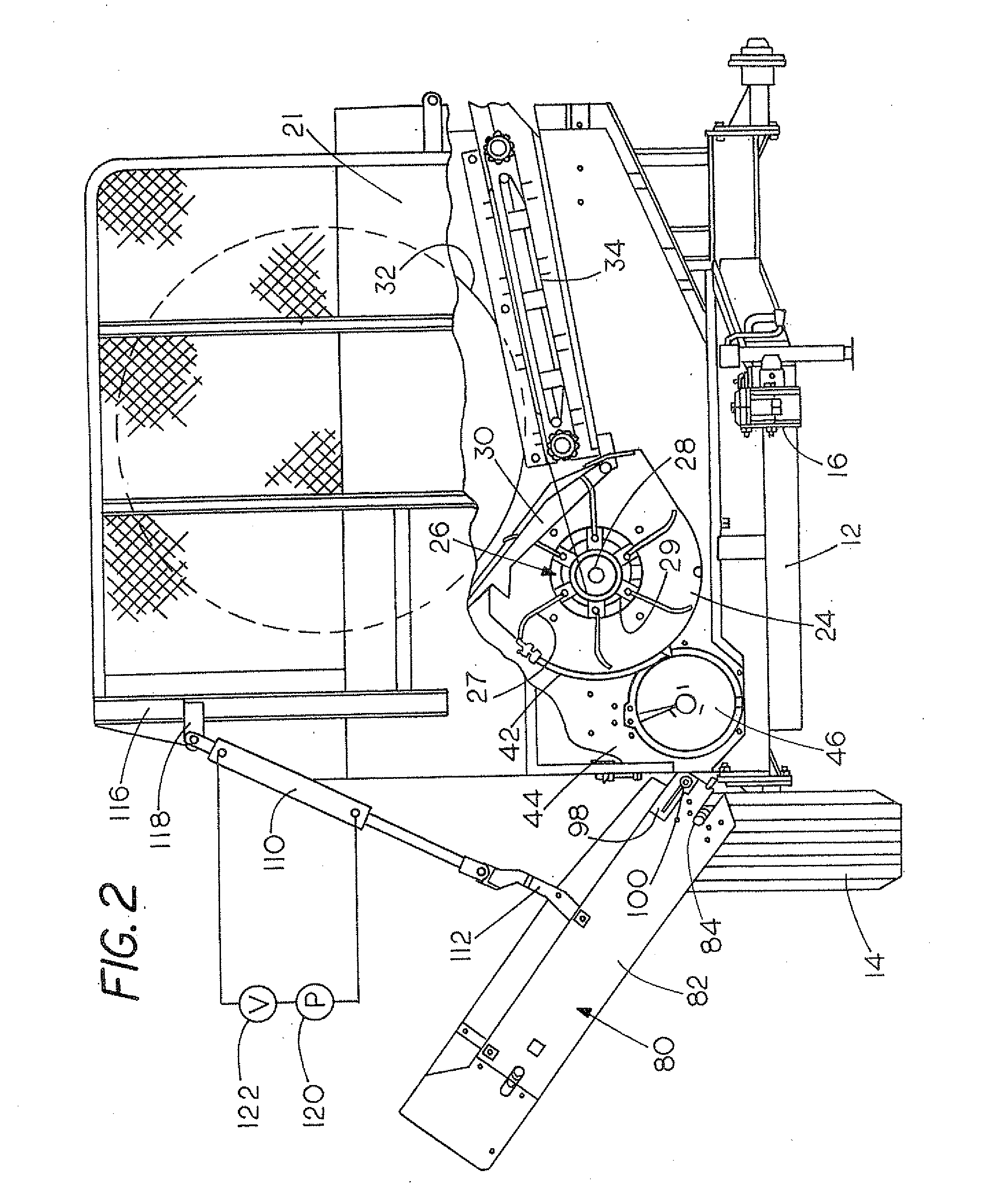
[0019]A main bale shredding housing 20 is supported on the frame 12 and has a forward end wall or plate 21 and a rear end wall or plate 22 A part cylindrical flail housing 24 extends between the front and rear walls, as shown in FIGS. 2 and 3. The front wall may be a partial mesh or screen. A shredding flail assembly 26 is provided with a lo...


PUM


Abstract

A bale shredder is mounted on a frame and has a flail that will shred material, such as hay, straw and silage, and an auger receives the shredded material and moves it toward a first end of the auger. The first end of the auger is surrounded by a chamber that has a first opening in an axial direction of the auger that opens into a fan or blower so that material going through the first opening is blown out of a discharge chute. An endless conveyor is mounted adjacent a second opening of the chamber, laterally of the auger, and is positioned to receive material from the second opening. Panels are provided for selectively blocking the first opening when the endless conveyor is to be moving material from the chamber, and for blocking the second opening when the fan is to be used for discharging material. The two different conveyors are selectively used for delivery of shredded material from the bale shredder.

Description

BACKGROUND OF THE DISCLOSURE[0001]The present disclosure relates to a discharge system for a shredder having a rotor that shreds bales of hay, straw, silage and the like, and which selectively uses a discharge blower or fan to receive shredded material from a bale processor that disintegrates the baled material and discharges the material out a discharge chute, or uses a side discharge conveyor that discharges the shredded material in a windrow, such as in a feed bunk or along the ground.[0002]In the prior art, bale shredders, such as those typically shown in U.S. Pat. Nos. 4,449,672 and 5,090,630, use a rotor with flails to disintegrate a bale of material and create a large air flow at the same time for discharging the material directly out to the side of the shredder.[0003]Other bale shredders have used a fan that creates a large air flow that will blow the shredded material through a discharge chute a long distance from the machine, for example over 100 feet.[0004]Various types o...

Claims


Application Information

Patent Timeline
Patent Type & Authority Applications(United States)
IPC IPC(8): B02C18/22B02C23/00
CPCA01F29/005Y10S241/605
Inventor BENNETT, PATRICK D.
Owner DURATECH INDS INT
Why Eureka
Try Eureka