Ventilation interface for sleep apnea therapy

Inactive Publication Date: 2007-06-21
WOOD THOMAS J
View PDF74 Cites 186 Cited by
  • Summary
  • Abstract
  • Description
  • Claims
  • Application Information

AI Technical Summary

Benefits of technology

[0020] When the nasal inserts are directly connected to the supply tubes, the nasal inserts may be even more thin-walled than when attached to a cannula body, resulting in an even greater volume of air supplied through the cannula body, up to a 20% increase in volume. In this case the supply tubes may be similar to heat-shrink tubing, being made from a very thin-walled thermoplastic is material that is lightweight and flexible so that the supply tubing may collapse when not in use, but will expand to a predetermined diameter under pressure applied by a ventilator.
[0021] Accordingly, it is an object of the invention to provide a ventilation interface for sleep apnea therapy having nasal inserts which seal against the nares and do not require a harness, head strap, or other external devices to maintain pressure for retaining the inserts in or against the patient's nostrils.
[0022] It is another object of the invention to provide a ventilation device having nasal inserts made of flexible, resilient plastic with a bead flange for retaining the inserts

Problems solved by technology

Sleep apnea is a potentially lethal affliction in which breathing stops recurrently during sleep.
Sleep apnea frequently results in-fitful periods of both day and night sleeping with drowsiness and exhaustion, leaving the patient physically and mentally debilitated.
However, there are problems with both of these interfaces.
The face mask requires a harness, headband, or other headgear to keep the mask in position, which many patient's find uncomfortable, particularly when sleeping.
The face mask must seal the mask against the patient's face, and may cause irritation and facial sores, particularly if the patient moves his head while sleeping, causing the mask to rub against the skin.
Face masks are also position dependent, and may leak if the mask changes position with movement of the patient's head.
This strips moisture from the mucosal wall during inspiration, thereby causing drying and a burn

Method used


Image

  • Ventilation interface for sleep apnea therapy
  • Ventilation interface for sleep apnea therapy
  • Ventilation interface for sleep apnea therapy

Examples


Embodiment Construction

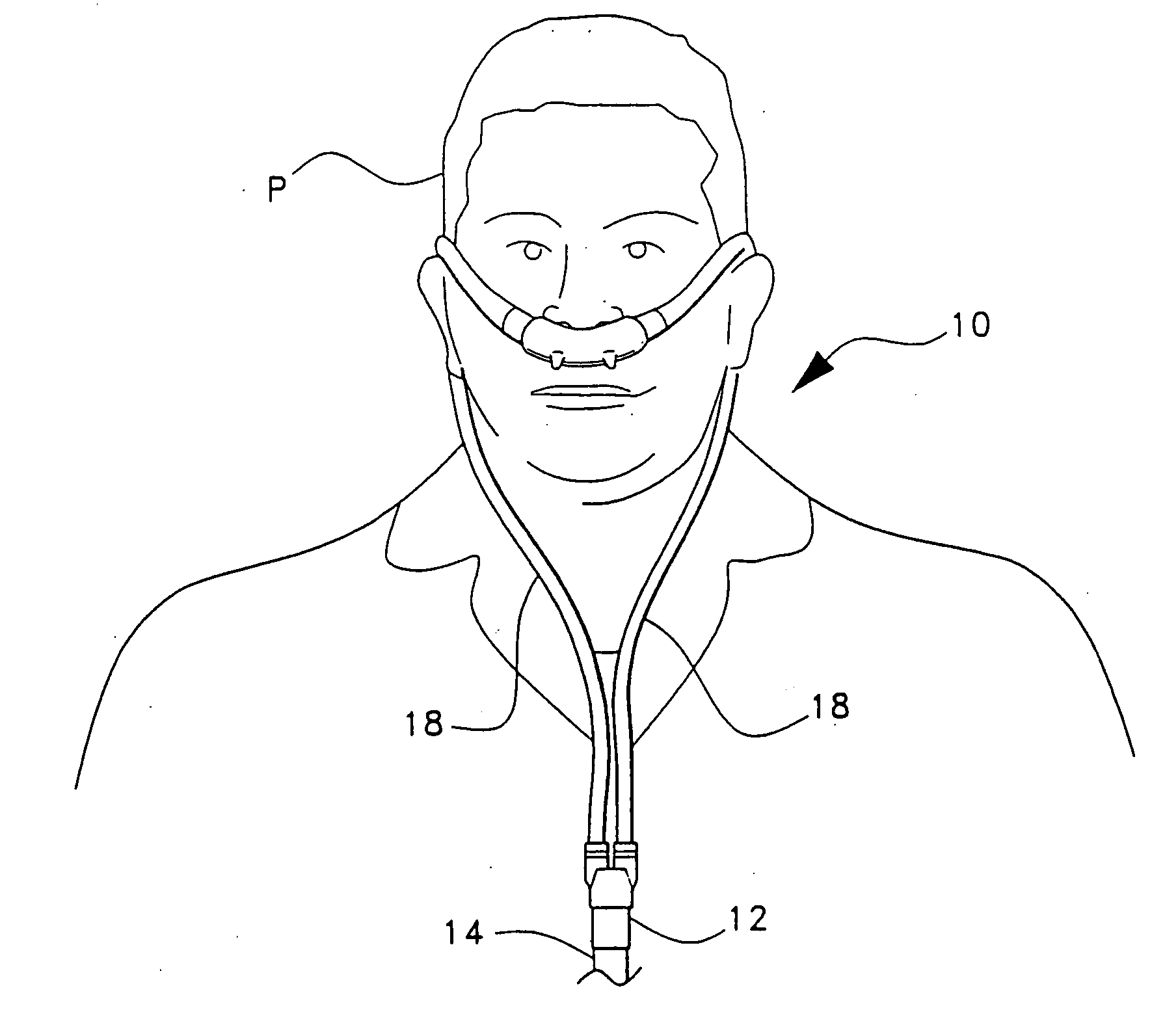
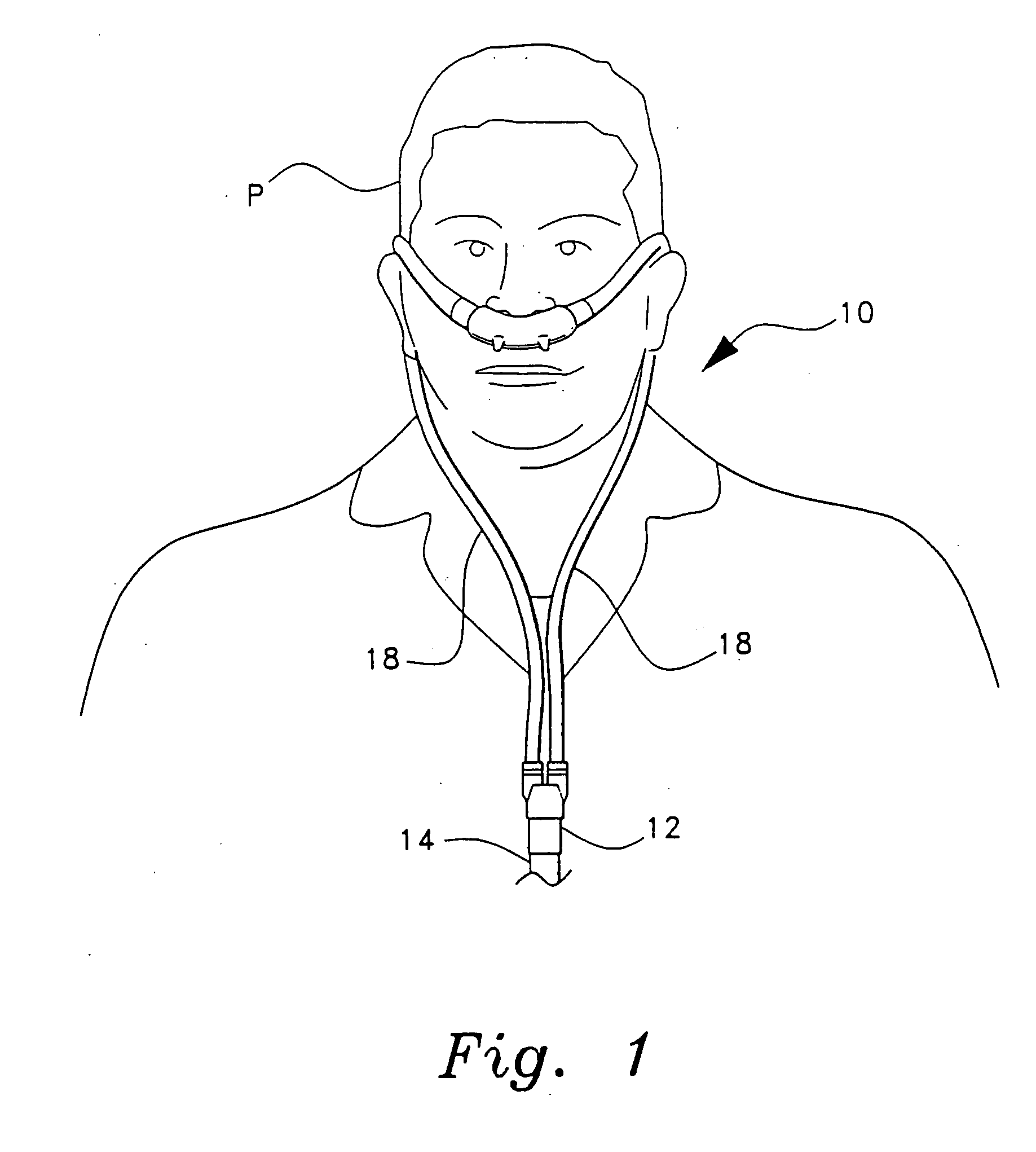
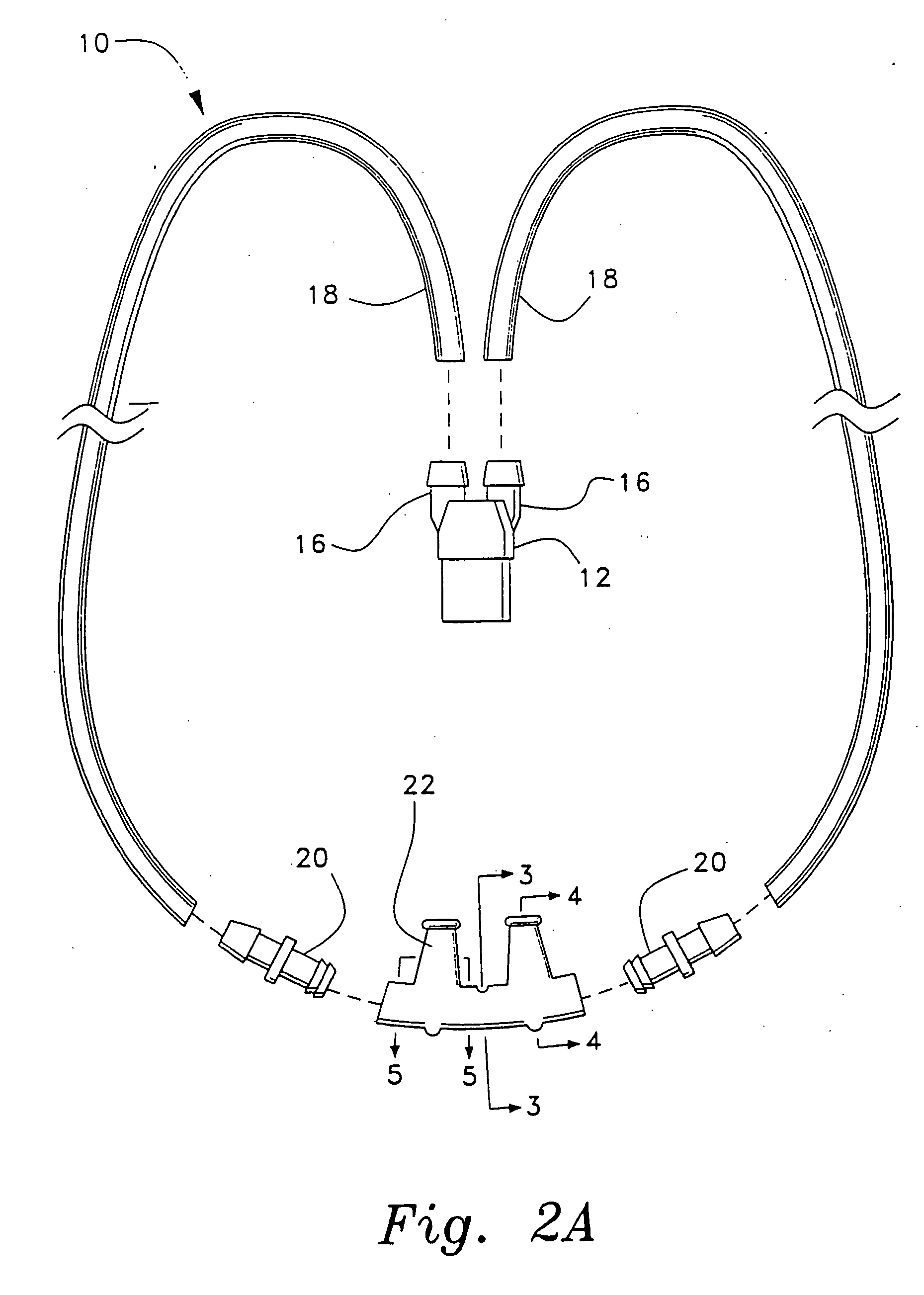
[0035] The present invention is a ventilation interface for sleep apnea therapy, designated generally as 10 in the drawings. The ventilation interface 10 provides an interface for connecting a ventilation device which provides positive airway pressure (either continuous, bilevel, or intermittent) with the patient's airways. As shown in FIGS. 1 and 2A, the ventilation interface 10 includes a conventional adapter or Y-connector 12 having a first end adapted to receive a supply hose 14 from a mechanical ventilator (not shown) and a second end having a pair of ports 16 with barbed connectors for attachment to two supply tubes 18. Supply tubes 18 may be, e.g., 0.3125″ ID (inside diameter) flexchem tubing, made of polyvinyl chloride or other conventional gas supply tubing. For sleep apnea therapy, the mechanical ventilator will usually supply room air at a pressure of between five and fifteen centimeters of water. The room air may be supplemented with oxygen if desired by splicing an oxyg...


PUM


Abstract

The ventilation interface for sleep apnea therapy interfaces a ventilation device to the patient's airways. The ventilation interface includes a pair of nasal inserts made from flexible, resilient silicone which are oval shaped in cross-section and slightly tapered from a base proximal the ventilation supply to the distal tip end. A bead flange is disposed about the exterior of each insert at the distal end of the insert. A bleed port for release of exhaled air is defined through a conical vent projecting normally to the path of the incoming air flow, and continues through a nipple extending to the exterior of the air conduit. In one embodiment, a pair of nasal inserts are integral with a nasal cannula body, with bleed ports axially aligned with each insert. In another embodiment, each insert is independently connected to a separate, thin-walled, flexible supply line.

Description

CROSS REFERENCE TO RELATED APPLICATIONS [0001] This is a continuation-in-part of application Ser. No. 09 / 524,371, filed Mar. 13, 2000.BACKGROUND OF THE INVENTION [0002] 1. Field of the Invention [0003] The present invention relates to ventilation devices, and particularly to a ventilation device having a nasal inserts which are inserted into the nostrils and seal against the nostrils without the aid of harnesses, head straps, adhesive tape or other external devices, and having exhalation ports designed to eliminate whistling noises, the ventilation interface having particular utility in various modes of therapy for obstructive sleep apnea. [0004] 2. Description of the Related Art [0005] Sleep apnea is a potentially lethal affliction in which breathing stops recurrently during sleep. Sleep apnea may be of the obstructive type (sometimes known as the pickwickian syndrome) in which the upper airway is blocked in spite of airflow drive; the central type with decreased respiratory drive;...

Claims


Application Information

Patent Timeline
IPC IPC(8): A61M16/00A61M15/08
CPCA61M16/0666A61M16/0057A61M16/20A61M16/06A61M16/0616A61M16/0694A61M16/0816A61M16/0833A61M16/201A61M2206/20
Inventor WOOD, THOMAS J.
Owner WOOD THOMAS J
Why Eureka
Try Eureka