
Blade structure of axial fan

a blade structure and fan technology, applied in the direction of liquid fuel engines, vessel construction, marine propulsion, etc., can solve the problems of increasing the product cost of getting a higher air pressure, limiting success, etc., to achieve a greater air volume, higher air pressure, and improved static pressure and air flow rate characteristic. q curve

Inactive Publication Date: 2015-06-04
APPLIED THERMAL FLUID ANALYSIS CENT LIMITED LIABILITY
View PDF5 Cites 11 Cited by
  • Summary
  • Abstract
  • Description
  • Claims
  • Application Information

AI Technical Summary

Benefits of technology

The present invention provides a blade structure for an axial fan that improves its performance by enhancing the static pressure and air flow rate (P-Q curve). This results in a higher air pressure and greater air volume, improving the efficiency of the fan. The blade structure includes multiple blades, with a separation between them and a second leading edge at a specific line location. This helps to maintain the flow above the first blade surface and reinforce the boundary layer at the downstream, reducing the thickness of the layer and enhancing the fan's efficiency. Additionally, the invention is cost-effective and easy to implement.

Problems solved by technology

However, a limited success is achieved up to now.
Thus, how to improve the working efficiency of blades without increasing the product cost for getting a greater air volume and a higher air pressure are important issues in the industry.

Method used


Image

  • Blade structure of axial fan
  • Blade structure of axial fan
  • Blade structure of axial fan

Examples


Embodiment Construction

[0018]In cooperation with attached drawings, the technical contents and detailed description of the invention are described thereinafter according to a number of preferable embodiments, being not used to limit its executing scope. Any equivalent variation and modification made according to appended claims is all covered by the claims claimed by the present invention.

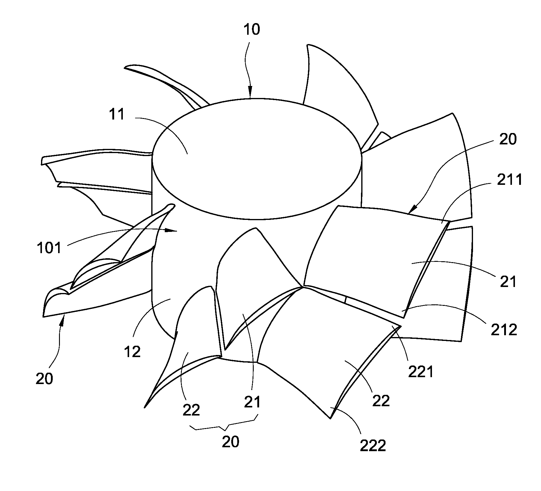
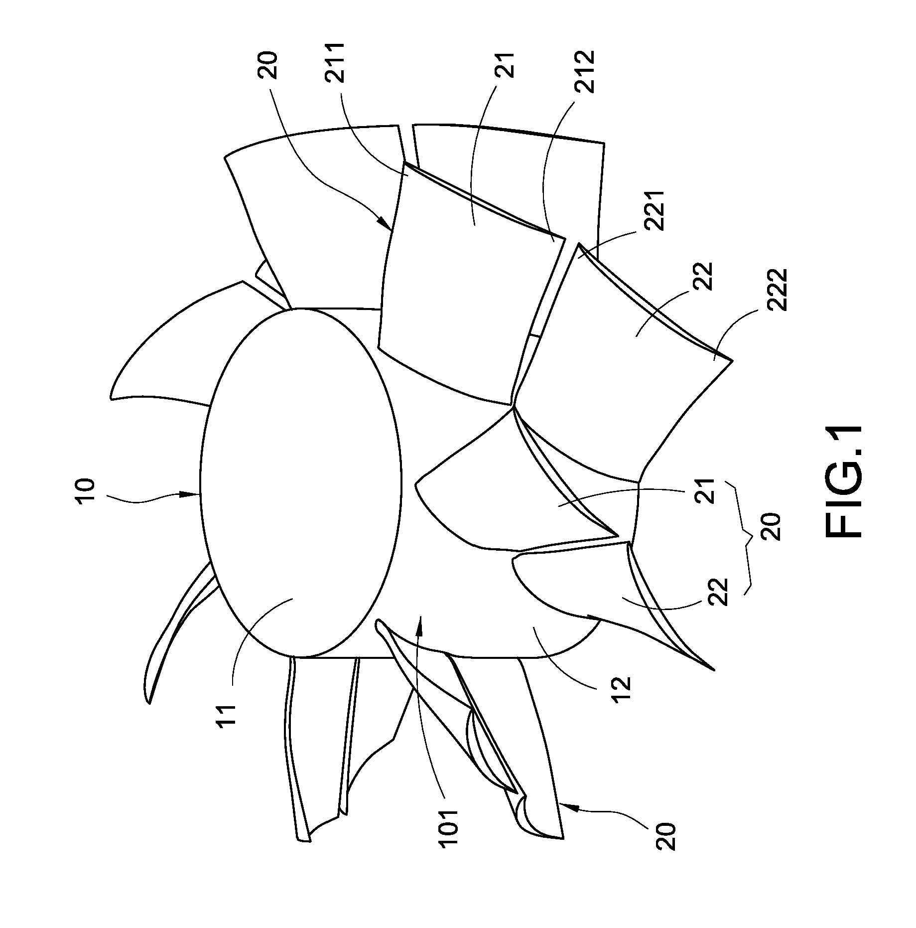
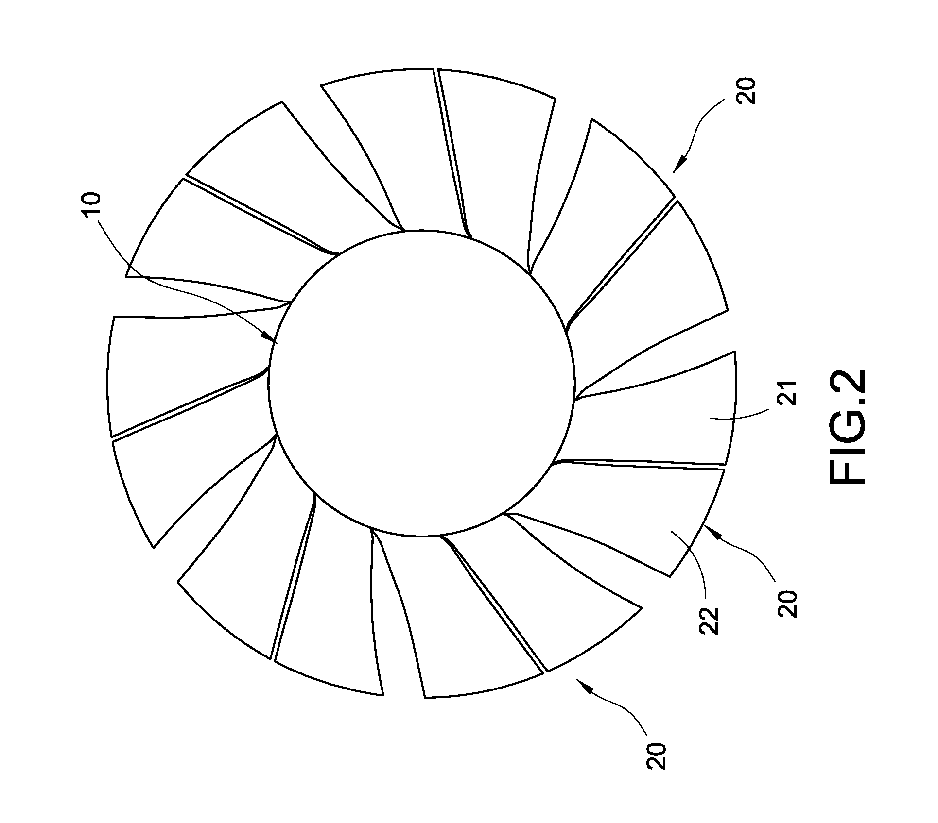
[0019]Please refer to FIG. 1 and FIG. 2, they depict a perspective schematic view and a top view of a blade structure of an axial fan of the present invention. The present invention provides a blade structure of an axial fan including a hub 10 and a plural of fan blades 20. The fan blades 20 are combined on the hub 10. The hub 10 is driven to rotate with the fan blades 20 to push surrounding fluid flowing.

[0020]The hub 19 is a cylinder including a top plate 11 and a side plate 12 extended from a periphery of the top plate 11, and the side plate 12 encloses one side of the top plate 11 for forming a peripheral surface 101...


PUM


Abstract

A blade structure of an axial fan is disclosed. The blade structure includes a hub and a plural of fan blades. The fan blades are disposed equidistantly on a periphery of the hub along a rotating direction of the hub. Each fan blade includes a first blade and a second blade. The first blade has a first leading edge and a first trailing edge, and the second blade having a second leading edge and a second trailing edge. A line connecting the first leading edge and the first trailing edge of each fan blade is a first chord line. The second leading edge is located at a line extended along the first chord line, and the separation between the first blade and the second blade is smaller than a distance of adjacent fan blades on the periphery of the hub.

Description

BACKGROUND OF THE INVENTION[0001]1. Field of the Invention[0002]The present invention generally relates to an axial fan and, in particular to a blade structure of an axial fan with high working efficiency.[0003]2. Description of Related Art[0004]Axial machine plays an important role in human industry. Fans, blowers, bumps, and propellers, for example, are used of axial blades for driving or transmitting fluid. Therefore, it is very important to improve the performance of axial machines for working efficiency and energy savings, and it's also a target for the industry continues to pursue.[0005]Take fans for an instance, an axial fan usually includes a motor, a hub and a plural of blades. The hub is rotated by the driving of the motor, and fluid is flown by the push of the blades. To improve the characteristic of static pressure and air flow rate (P-Q curve) of the axial fan for pushing the fluid, a best performance is achieved through adjusting the size and angle of the blades. Howev...

Claims


Application Information

Patent Timeline
Patent Type & Authority Applications(United States)
IPC IPC(8): F04D29/38
CPCF04D29/384F04D19/002
Inventor TZENG, YIH-WEI
Owner APPLIED THERMAL FLUID ANALYSIS CENT LIMITED LIABILITY
Learn More