Motor of washing machine

A washing machine and motor technology, applied in the field of outer rotor type magnetic induction motors, can solve the problems of shortening the life of the motor 30, increasing the material cost, increasing the cost of the motor 30, etc., so as to prevent the decline of the motor efficiency, reduce the unit cost and reduce the material cost. Effect

Active Publication Date: 2011-09-28
LG ELECTRONICS INC
View PDF2 Cites 2 Cited by
  • Summary
  • Abstract
  • Description
  • Claims
  • Application Information

AI Technical Summary

Problems solved by technology

[0026] However, since the rotor magnet 42 is combined with the inner peripheral surface of the rotor frame 40 by using an adhesive (not shown), the prior art motor for the washing machine has a problem that when the adhesive force of the adhesive 'B' becomes low, By the rotational force of the motor 30, the rotor magnet 42 is separated from the opened upper part of the rotor frame 40.
[0027] That is, the adhesive tends to change in composition over time, or is affected by heat from the motor 30, resulting in poor adhesion
Therefore, if the adhesive force of the adhesive deteriorates, the rotor magnet 42 will be separated due to the rotational force of the rotor frame 40, so the reliability of the motor 30 is reduced, and the life of the motor 30 is also shortened.
[0028] Moreover, the application of a special adhesive with good thermal resistance and durability increases the cost of the motor 30
[0029] Secondly, the prior art motors for washing machines have a problem that the rotor frame 40 is distorted or deformed into an oval shape due to the centrifugal force of the high-speed rotation of the rotor frame 40.
[0030] On the other hand, if the rotor frame 40 is made to have a sufficient thickness to strengthen the strength of the rotor frame 40 in order to solve the above-mentioned problems, even if deformation caused by centrifugal force can be prevented, the material cost of the rotor frame 40 increases, and the motor 30 is increased. cost, and increased the weight of the rotor frame 40, thereby reducing the efficiency of the motor 30
[0031] Secondly, since the prior art motor used in the washing machine has such a structure that there is a gap 'G' between the stator 32 and the rotor magnet 42 which cannot be seen from the outside of the motor, it is very likely that the gap 'G' is not The rotor 34 is assembled in a uniform state, and even if the gap 'G' becomes uneven due to the use of the motor 30 for a long time, it is difficult to check this and adjust the state
[0032] The non-uniform gap 'G' causes the efficiency of the motor 30 to decrease and can cause damage to the motor 30 if the stator 32 and the rotor magnet 42 collide
[0033] In particular, although it is important to maintain the gap 'G' of the motor 30, the maintenance of the gap 'G' is very difficult and cumbersome, because inspection and adjustment for the gap 'G' is only possible in the rotor frame 40 carried out in the disassembled state
[0034] Moreover, in prior art motors used in washing machines, due to the heat loss generated by the stator 32 and rotor 34 as the motor 30 runs for a long time, the temperature rise in the motor 30 impairs the performance of the motor 30.
[0035] In order to solve this problem, although the lower air holes 40b and the lower blades 40c are formed on the rotor frame 40 of the motor 30 for guiding outside air thereto to cool the motor 30, the lower air holes 40b and the lower blades 40c cannot provide sufficient air. flow rate to prevent the temperature rise of the motor 30, especially when turning the motor 30 for pumping water, the overheating of the motor 3 will further reduce the efficiency
[0036] In particular, since the lower air holes 40b and the lower blades 40c blow air only toward the lower side of the motor 30, the cooling of the upper part of the motor 30 is very slow.

Method used


Image

  • Motor of washing machine
  • Motor of washing machine
  • Motor of washing machine

Examples


Embodiment Construction

[0095] Embodiments of the present invention will be described with reference to the drawings.

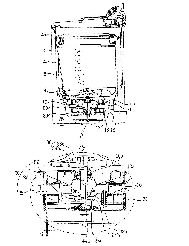
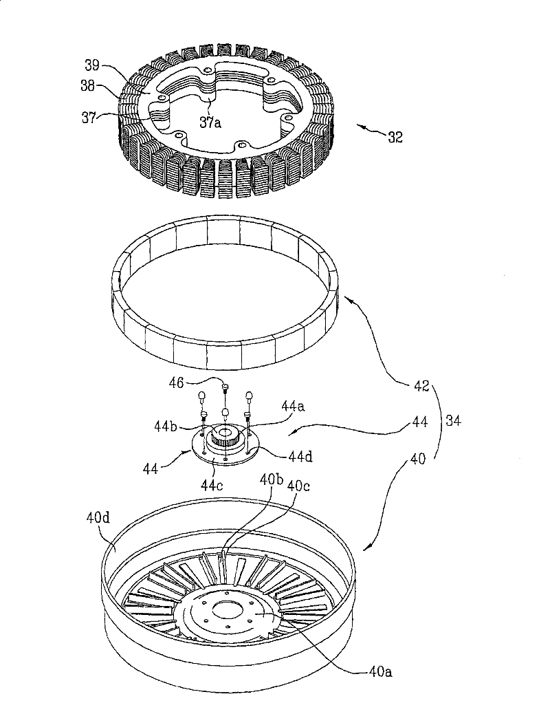
[0096] Figure 4 shows a side sectional view of a washing machine with a motor according to a preferred embodiment of the invention applied thereto, Figure 5 and 6 respectively expressed in Figure 4 Perspective and cutaway views of key parts shown in , and Figure 7 expressed in Figure 5 A cross-section of line A-A in middle.

[0097] see Figures 4 to 7 , the washing machine includes a cabinet 52 forming its exterior; an outer tub 54 suspended inside the cabinet 52 by means of a support member 54a, which has a space for holding washing water inside; an inner tub 58 rotatably mounted in the outer tub 54, with a commutator installed at its bottom 56, there are water holes on the side wall; the motor 60 located below the outer tub 54, which provides driving force to the rotating commutator 56 and the inner tub 58; and the power transmission unit 80 located between the motor 6...


PUM


Abstract

The present invention relates to a motor (60) for a washing machine for enhancing rigidity of a rotor frame (122), easy verification and adjustment of a gap, and improving a cooling performance of the motor (60). To achieve the objects of the present invention, a motor (60) for a washing machine includes a stator (110) having an AC power applied thereto, a rotor core (124) on an outer side of thestator (110) mounted so as to be rotatable by interaction of electromagnetic force with respect to the stator (110), a rotor frame (122) arranged to surround the outer side of the stator (110), rotorcore securing means (154,155) formed along a side of the rotor frame (122) for seating, and securing the rotor core (124), and preventing the rotor core (124) from moving in up / down directions, strength reinforcing means (148) for improving strength of the rotor frame, and gap verifying means (156) provided to the rotor frame (122) for verifying a gap between the rotor.

Description

technical field [0001] The present invention relates to an outer rotor type magnetic induction motor for a washing machine, and more particularly, to an outer rotor type magnetic induction motor for a washing machine with an improved rotor structure. Background technique [0002] Generally, a washing machine washes clothes through steps of washing, rinsing, centrifugal spinning, drying, etc., and removes dirt from clothes and bedding (hereinafter referred to as clothes) held in a washing tub by the action of water and detergent. [0003] figure 1 Illustrates a section of a washing machine to which a motor of the related art is applied, figure 2 A perspective view of a related art washing machine motor is illustrated. [0004] refer to figure 1 , the washing machine of the related art is provided with a cabinet 2 to form its exterior; an outer tub 4 with a support member 4a suspended in the cabinet 2 has a space for holding washing water; an inner tub 8 rotatably installe...

Claims


Application Information

Patent Timeline
Patent Type & Authority Patents(China)
IPC IPC(8): H02K9/06H02K1/32H02K5/173D06F37/30H02K5/20H02K21/12
CPCH02K1/32H02K5/20D06F37/02H02K9/22D06F37/304H02K1/30H02K9/06H02K15/03
Inventor 朴容奭
Owner LG ELECTRONICS INC
Why Eureka
Try Eureka