Aerostatic Buoyancy Control System

a control system and buoyancy technology, applied in rigid airships, aircrafts, vehicles, etc., can solve the problems of limited heat, limited tensile strength, and affecting the lift of balloons, so as to reduce aerostatic lift, increase aerostatic lift, and high tensile strength

Inactive Publication Date: 2009-05-07
VOORHEES MICHAEL TODD
View PDF51 Cites 23 Cited by
  • Summary
  • Abstract
  • Description
  • Claims
  • Application Information

AI Technical Summary

Benefits of technology

[0014]A system allowing for the active management of aerostatic lift in buoyant and semi-buoyant aerial vehicles comprised of a high tensile-strength outer pressure cell of a given volume and an inner compression cell of only slightly smaller dimensions. The inner compression cell is filled with a lifting gas, such as helium or hydrogen, to some fractional volume of its maximum, allowing for expansion of the lifting gas at different operational altitudes. When a reduction in aerostatic lift is desired, external air is compressed through the use of air handling means, and introduced into the outer pressure cell through a directional valve that prevents the pressurized air from leaving the pressure cell. When increased aerostatic lift is once again desired, the valve system may release all or a part of the pressurized air in the pressure cell, allowing the lifting gas to expand thereby displacing a greater volume of air and increasing lift. Importantly, no appreciable pressure differential is imposed across the inner compression cell membrane containing the lifting gas; therefore permeation rates are kept to a minimum. As the induced pressure is relatively small, little work is performed on the gas, and thus less energy is required than for high-pressure systems. Also, because the inner cell is concentric with the outer cell, it is unnecessary to house external pressure chambers enclosed within the volume of the hull, resulting in more available lift for a given size of aircraft.

Problems solved by technology

In hot air balloons this is achieved through variable input of heat, however in gas balloons, it has largely been limited to the venting of lifting gas or the release of ballast.
This process alters the density of air inside the balloon and thus affects the balloon's lift.
The method was difficult to control and provided limited heat, but effectively demonstrated the potential of hot air balloons.
In these systems buoyancy control has largely been limited to the venting of lifting gas and the release of ballast.
Muesnier's design was never built, partly due to his early death nine years later, but also due to technical challenges.
The availability of air pumps with high flow rates, sufficient pressure, and of lightweight construction would not occur for decades and the tensile strength and impermeability of fabric of the time was insufficient for sustaining pressure differentials necessary for significant buoyancy control.
The only significant modifications have been a reduction in scale of the ballonet and the combined use of both fore and aft ballonets to allow for trim adjustment (pitching the nose up or down), which would then impart aerodynamic forces to adjust altitude, but the ballonet would not serve as an effective direct lift control system for other than minor adjustments.
Additionally, the airship could be flown with the nose pitched up or down by using aerodynamic elevators, creating positive or negative aerodynamic lift, but in so doing inducing significant drag, thus reducing the efficiency of the airship.
It became immediately apparent that the practice of venting helium would be quite expensive and other techniques were required for economical operation.
While these methods were sufficient for replacing the weight of fuel consumed in flight, it could not be employed for significant asymmetrical cargo operations.
It has generally been found that such pressurization requires heavier and more energy intensive compressors, heavy storage containers, and often the use of gas cooling and heating systems to remove or add heat to the gases undergoing anisothermal volumetric change.
Such a system is complex, expensive, heavy, and susceptible to fouling, and has many practical limitations including the availability of water at cargo destinations.
Such hybrid designs have been proposed specifically to handle the asymmetric lift problem, however they introduce more problems than they solve.
Namely, the hybrid suffers induced drag that results from aerodynamic lift and requires forward momentum to become airborne.
The significant decrease in efficiency due to induced drag alone makes the hybrid vehicle approach economically less attractive.

Method used


Image

  • Aerostatic Buoyancy Control System
  • Aerostatic Buoyancy Control System
  • Aerostatic Buoyancy Control System

Examples


Embodiment Construction

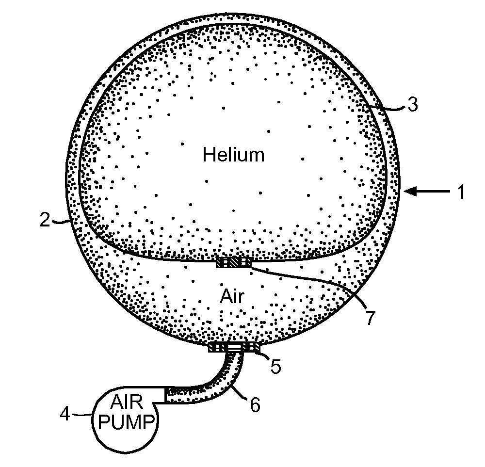
[0025]Referencing FIG. 1b, this invention is an aerostatic buoyancy control system 1 allowing for the active management of aerostatic lift in buoyant and semi-buoyant aerial vehicles. It utilizes an outer pressure cell 2 made of high tensile strength air-impermeable membrane of a given volume, and an inner compression cell 3 made of flexible lifting-gas-impermeable membrane and of only slightly smaller dimensions than the outer pressure cell 2.

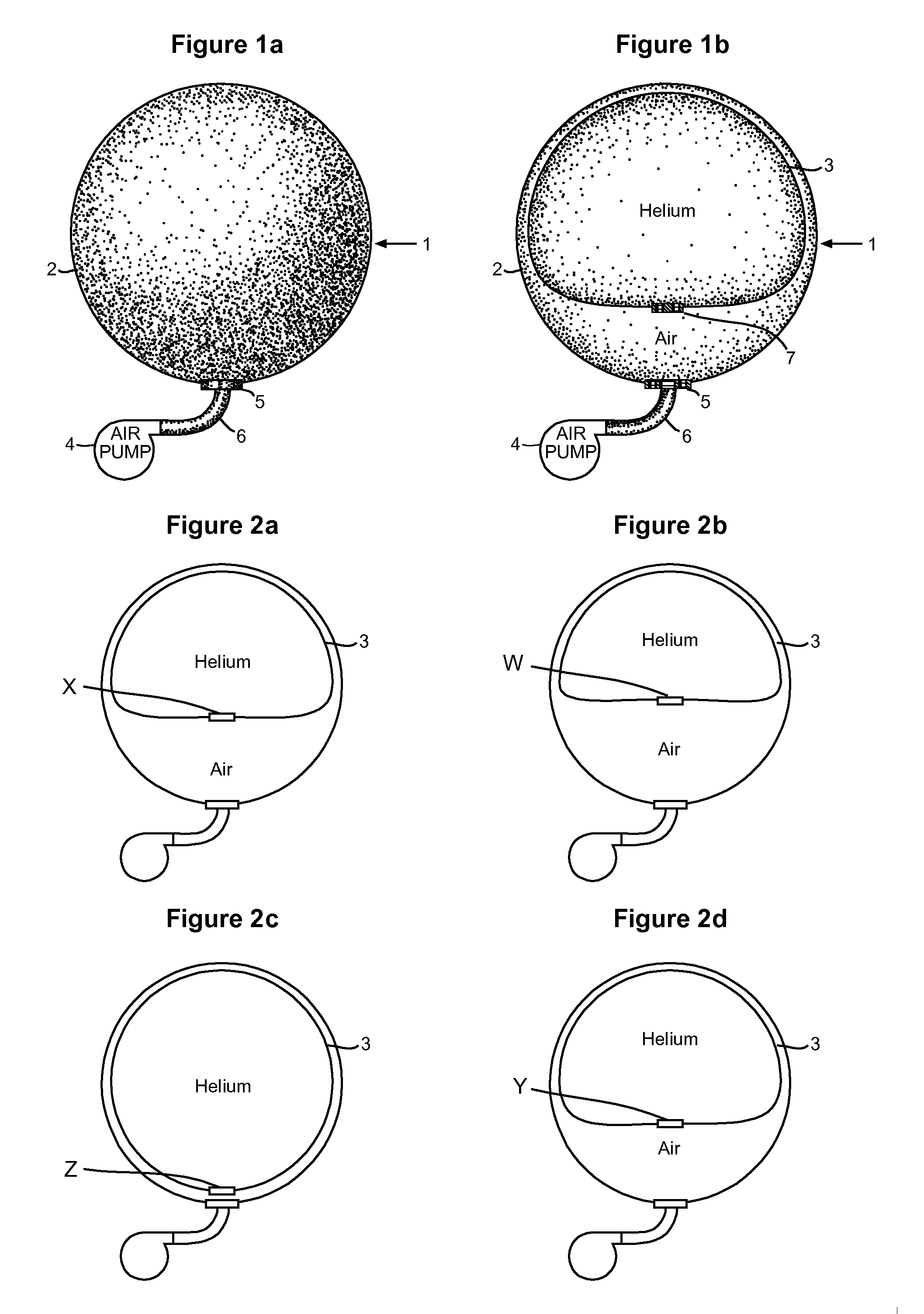
[0026]The inner compression cell 3 is filled with a lifting gas, such as helium or hydrogen, via a gastight valve system 7 to some fractional volume of its maximum capacity at Mean Sea Level, as shown in FIG. 2a, which depicts a 75% fill, with the lower portion of the inner compression cell 3 reaching spatial equilibrium at position X. This allows for expansion of the lifting gas at different operational altitudes. The outer pressure cell 2 communicates with the outside atmosphere via a closeable and directional valve system 5. When the valve ...


PUM


Abstract

A system allowing for the active management of aerostatic lift in buoyant and semi-buoyant aerial vehicles comprised of a high tensile-strength outer pressure cell of a given volume and an inner compression cell of only slightly smaller dimensions. The inner compression cell is filled with a lifting gas, such as helium or hydrogen, to some fractional volume of its maximum, allowing for expansion of the lifting gas at different operational altitudes. When a reduction in aerostatic lift is desired, external air is compressed through the use of air handling means, and introduced into the outer pressure cell through a directional valve that prevents the pressurized air from leaving the pressure cell. When increased aerostatic lift is once again desired, the valve system may release all or a part of the pressurized air in the pressure cell, allowing the lifting gas to expand thereby displacing a greater volume of air and increasing lift.

Description

CROSS-REFERENCE TO RELATED APPLICATIONS[0001]Not ApplicableSTATEMENT REGARDING FEDERALLY SPONSORED RESEARCH OR DEVELOPMENT[0002]Not ApplicableTHE NAMES OF THE PARTIES TO A JOINT RESEARCH AGREEMENT[0003]Not ApplicableINCORPORATION-BY-REFERENCE OF MATERIAL SUBMITTED ON A COMPACT DISC[0004]Not ApplicableBACKGROUND OF THE INVENTION[0005]1. Field of the Invention[0006]Application of this invention would be useful in manned and unmanned airships and balloons or other buoyant and semi-buoyant vehicles, and relates to the reversible adjustment of aerostatic lift via pneumatic means without the use of offsetting ballast.[0007]2. Description of the Related Art[0008]The ability to economically adjust aerostatic lift has long been a goal of lighter-than-air vehicle designers. It is especially useful in asymmetric cargo operations where payloads may be exchanged without the use of offsetting ballast. Operations such as transport of materiel from military bases into a combat theater of operations...

Claims


Application Information

Patent Timeline
Patent Type & Authority Applications(United States)
IPC IPC(8): B64B1/58
CPCB64B1/58B64B1/38
Inventor VOORHEES, MICHAEL TODD
Owner VOORHEES MICHAEL TODD
Why Eureka
Try Eureka