
Radiation signal-processing unit and radiation detector provided with the same

a radiation detector and signal processing technology, applied in the direction of radiation intensity measurement, instruments, x/gamma/cosmic radiation measurement, etc., can solve the problems of inability to detect fluorescence in time, incorrect identification of the position where fluorescence is generated, and conventional radiation detection noted abov

Inactive Publication Date: 2011-09-15
SHIMADZU CORP
View PDF10 Cites 7 Cited by
  • Summary
  • Abstract
  • Description
  • Claims
  • Application Information

AI Technical Summary

Benefits of technology

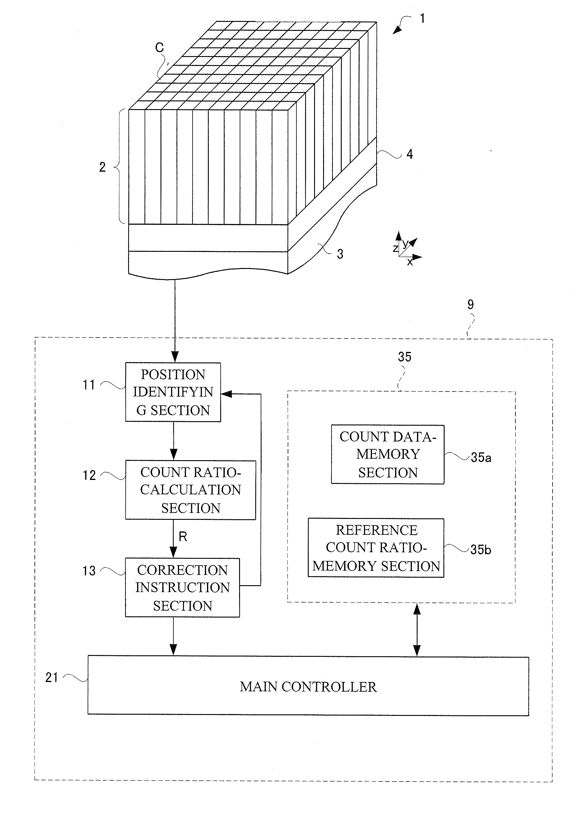
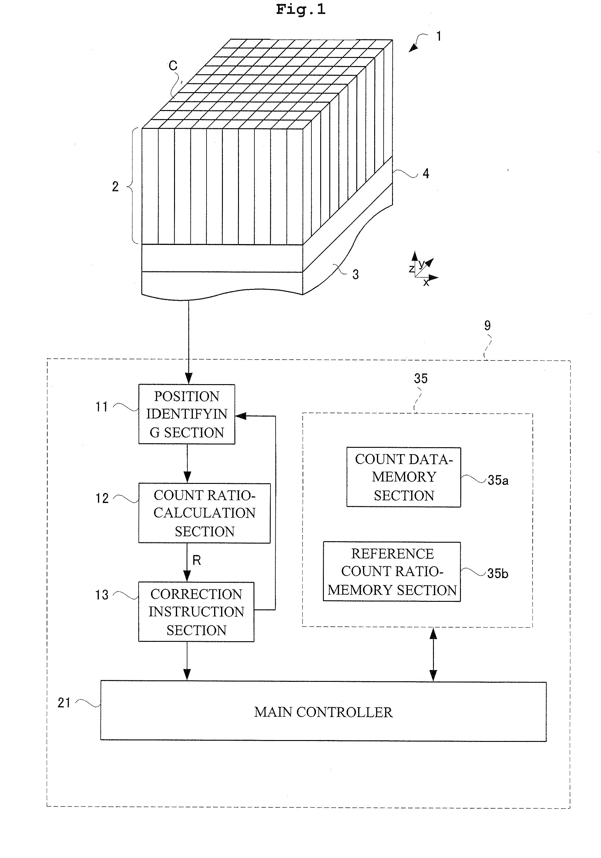
The invention is a radiation signal-processing unit that can identify the position of an incident gamma-ray by using a scintillator to convert radiation into fluorescence. The unit includes a position identifying device, a count data-memory device, a count ratio-calculation device, a reference count ratio-memory device, and a correction instruction device. The correction instruction device reads the reference count ratio from the reference count ratio-memory device and compares it with the count ratio calculated from the detection data. This allows for accurate position identification even when there is afterglow from fluorescence. The unit can repeat the correction process every few seconds to ensure accurate position identification. The invention provides a solution to the problem of identifying the position of an incident gamma-ray while accounting for afterglow.

Problems solved by technology

However, the conventional detection of radiation noted above has a following drawback.
Specifically, more doses of radiation entering into the radiation detector 51 may lead to incorrect identification of a position where fluorescence is generated.
This drawback concerns to a calculation process of the center of gravity in the luminous flux of fluorescence.
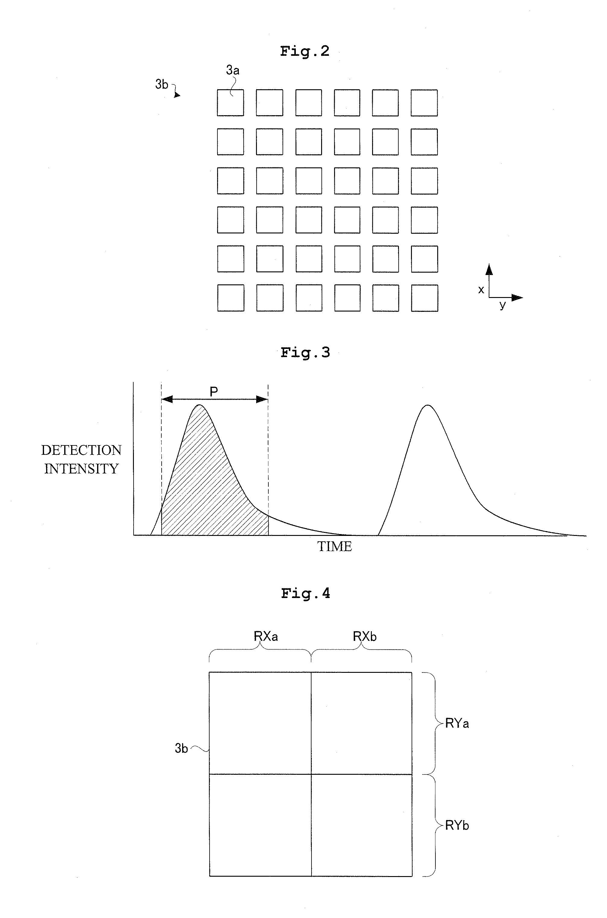
Upon detecting of radiation, it takes much time to detect fluorescence in consideration of such afterglow disappearance.
As above, according to the conventional art, the afterglow of fluorescence causes incorrect identification of the fluorescence generating position.

Method used


Image

  • Radiation signal-processing unit and radiation detector provided with the same
  • Radiation signal-processing unit and radiation detector provided with the same
  • Radiation signal-processing unit and radiation detector provided with the same

Examples


Embodiment Construction

[0038]The invention is described more fully hereinafter with reference to the accompanying drawings, in which embodiments of the invention are shown. This invention may, however, be embodied in many different forms and should not be construed as limited to the embodiments set forth herein. Rather, these embodiments are provided so that this disclosure is thorough, and will fully convey the scope of the invention to those skilled in the art. In the drawings, the size and relative sizes of layers and regions may be exaggerated for clarity. Like reference numerals in the drawings denote like elements.

[0039]Next, description will be given of one embodiment of a radiation signal-processing unit and a radiation detector according to this invention. Here, gamma rays are an example of radiation.

[0040]As shown in FIG. 1, the radiation detector 1 according to Embodiment 1 includes a scintillator 2 having scintillation counter crystals C arranged vertically and transversely, a light detector 3...


PUM


Abstract

A radiation signal-processing unit including a position identifying device for identifying an incident radiation position in a radiation detector; a count data-memory device for storing positional information outputted from the position identifying device, a count ratio-calculation device for calculating a count ratio based on the positional information stored in the count data-memory device, a reference count ratio-memory device for memorizing a reference count ratio as the count ratio calculated under a state where fluorescence to be detected does not overlap each other temporally, and a correction instruction device for reading the reference count ratio from the reference count ratio-memory device and comparing the ratio with the count ratio, thereby instructing execution of correction of a radiation generating position to the position identifying device.

Description

BACKGROUND OF THE INVENTION[0001](1) Field of the Invention[0002]This invention relates to a radiation signal-processing unit for correcting detection signals of annihilation radiation-pairs, and a radiation detector provided therewith. More particularly, this invention is directed to a radiation signal-processing unit that allows correction of a detection position of radiation, and a radiation detector provided therewith.[0003](2) Description of the Related Art[0004]Description will be given of a specific construction of a conventional positron emission tomography (PET) device for imaging distribution on radiopharmaceutical. The conventional PET device includes a radiation ring having radiation detectors arranged circularly for detecting radiation. The detector ring detects a pair of radiation (an annihilation radiation-pair) having opposite directions to each other that is emitted from inside of a subject.[0005]Next, description will be given of a construction of the radiation det...

Claims


Application Information

Patent Timeline
Patent Type & Authority Applications(United States)
IPC IPC(8): G01T1/202G06F19/00
CPCG01T1/2928G01T1/202
Inventor OHI, JUNICHIFURUTA, MASAFUMISATO, MASANOBU
Owner SHIMADZU CORP
Learn More