Automatic frequency calibration circuit and automatic frequency calibration method
- Summary
- Abstract
- Description
- Claims
- Application Information
AI Technical Summary
Benefits of technology
Problems solved by technology
Method used
Image


Examples
Embodiment Construction
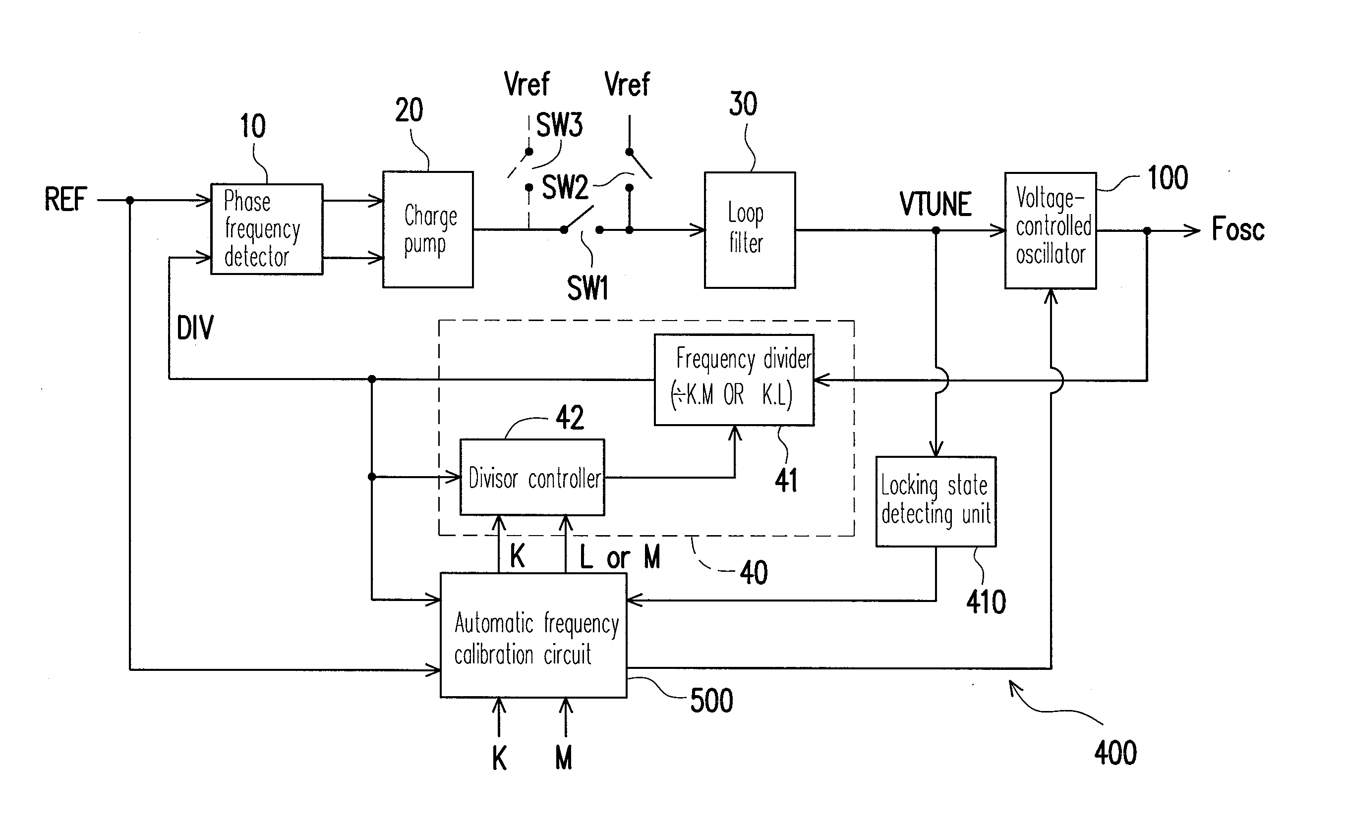
[0026]FIG. 4 is a functional block diagram illustrating a frequency synthesizer according to an exemplary embodiment of the present disclosure. The frequency synthesizer 400 includes a phase frequency detector (PFD) 10, a charge pump (CP) 20, a loop filter 30, a voltage-controlled oscillator 100, a frequency dividing unit 40 and an automatic frequency calibration circuit 500. The automatic frequency calibration circuit 500 can control a connecting state / connecting states of one or a plurality of switches of a switched-capacitor bank 112 within the VCO 100. Namely, the automatic frequency calibration circuit 500 can select one of capacitor configurations of the VCO 100 to set the VCO 100. The VCO 100 correspondingly generates an output frequency Fosc in response to a control voltage VTUNE. In the present exemplary embodiment, a first switch SW1 is disposed between the CP 20 and the loop filter 30, and a second switch SW2 and a third switch SW3 are disposed at two ends of the first sw...
PUM
 Abstract
Description
Claims
Application Information
 - R&D
- Intellectual Property
- Life Sciences
- Materials
- Tech Scout
- Unparalleled Data Quality
- Higher Quality Content
- 60% Fewer Hallucinations
Browse by: Latest US Patents, China's latest patents, Technical Efficacy Thesaurus, Application Domain, Technology Topic, Popular Technical Reports.
© 2025 PatSnap. All rights reserved.Legal|Privacy policy|Modern Slavery Act Transparency Statement|Sitemap|About US| Contact US: help@patsnap.com