
High-precision radio frequency ranging system

a radio frequency ranging and high-precision technology, applied in the field of radio frequency ranging systems, can solve the problems of gps signals being either unavailable or actively denied to a potential user, a type of system practicable, and a significant drawback

Active Publication Date: 2011-09-15
ENSCO INC
View PDF13 Cites 12 Cited by
  • Summary
  • Abstract
  • Description
  • Claims
  • Application Information

AI Technical Summary

Benefits of technology

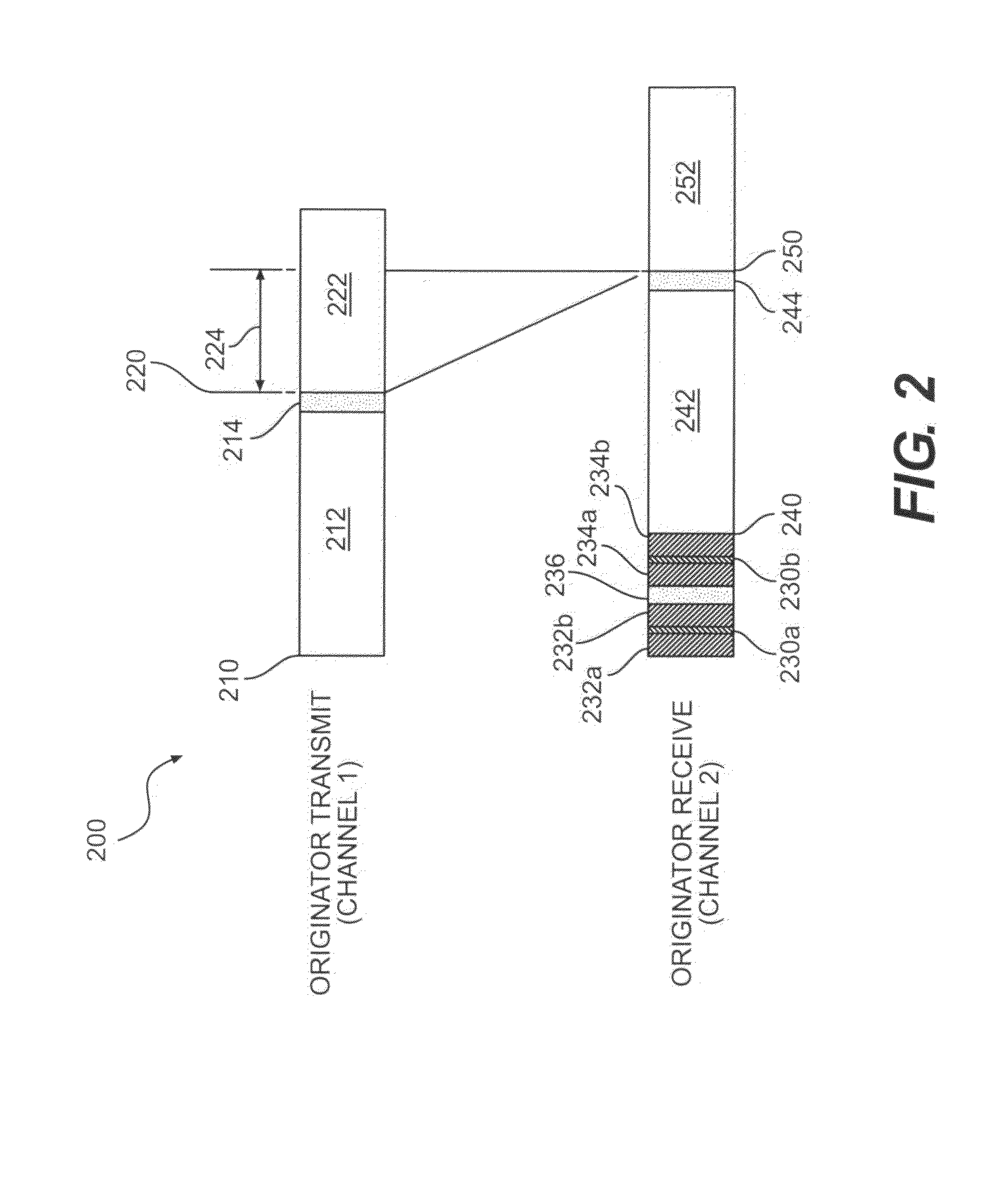
The present patent discusses methods for estimating the distance between a first radio (originator) and a second radio (transponder) using a coarse time measurement and a fine time adjustment. The coarse time measurement is calculated by transmitting a message and receiving a response, while the fine time adjustment is calculated by analyzing peak error measurements during a time period. The technical effects of the patent include improved accuracy in estimating the distance between the two radios and improved efficiency in calculating the fine time adjustment.

Problems solved by technology

In many situations, however, GPS signals are either unavailable or actively denied to a potential user.
Maintaining a system of clocks synchronized to the level of accuracy required to make this type of system practicable for ranging purposes represents a significant drawback.
While CW systems, such as tellurometers, enable long distance ranging in the tens of kilometers and accuracies of 1 cm at a distance of 1 km in low multipath environments, these systems often suffer from poor multipath performance, susceptibility to jamming, have a high probability of detection and interception, and tend to cause interference to other communications systems.
When UWB systems are constrained to operate within FCC regulations however, their range is typically limited to a few hundred meters using directional antennas in low multipath environments, and typically much less than 100 meters indoors with omni-directional antennas.
UWB systems also require complex RF electronics which can drive up system cost and risk.

Method used


Image

  • High-precision radio frequency ranging system
  • High-precision radio frequency ranging system
  • High-precision radio frequency ranging system

Examples


Embodiment Construction

[0036]Using the methods and apparatus described below, an RF round-trip time-of-flight asynchronous direct-sequence spread spectrum (DSSS) system can be designed to operate as an FCC unlicensed radio in the ISM bands. However, such a system is flexible in spectrum usage, and not tied to any particular band. Such a system would allow unlicensed operation, relatively long range, and relatively precise measurements.

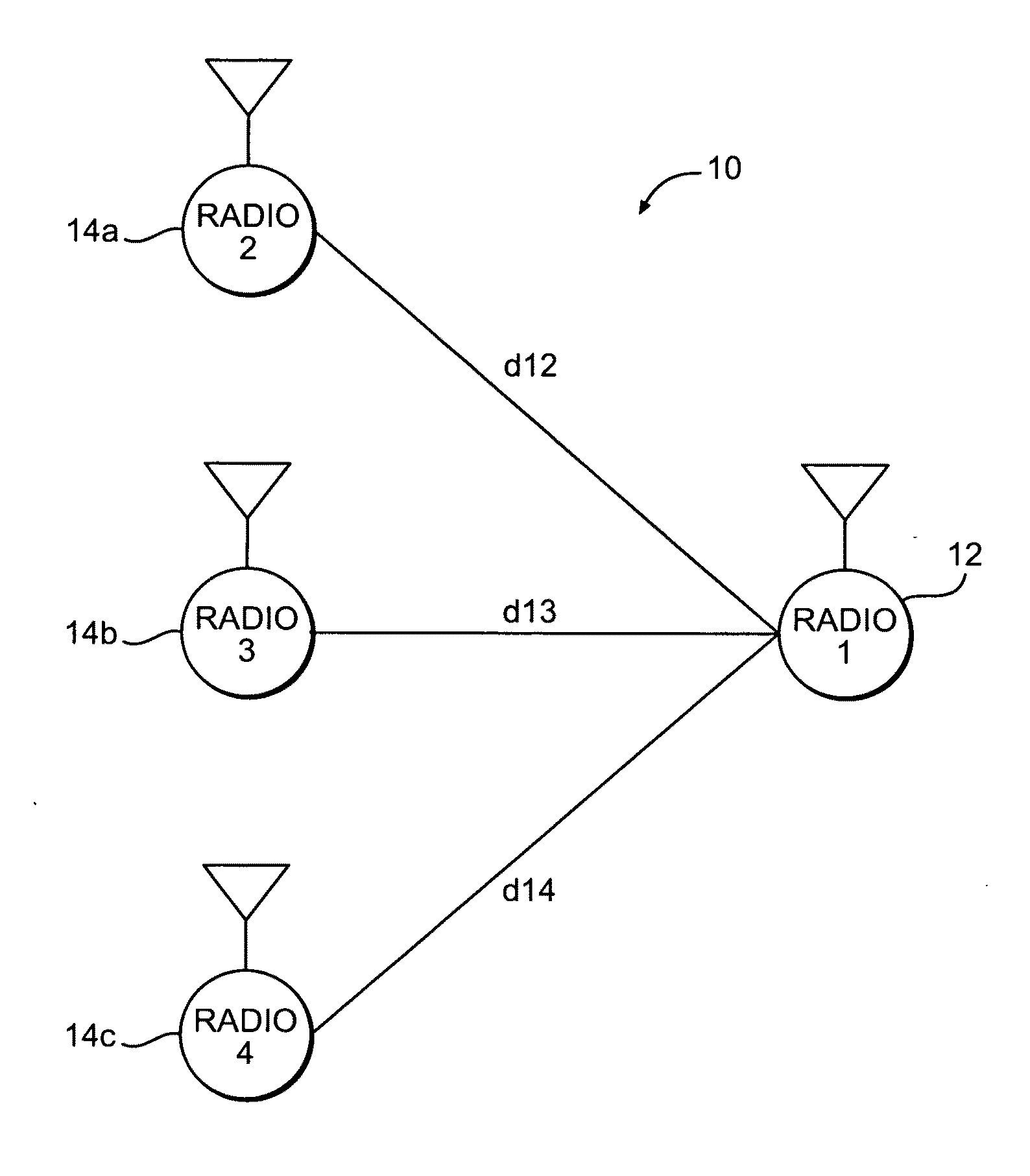
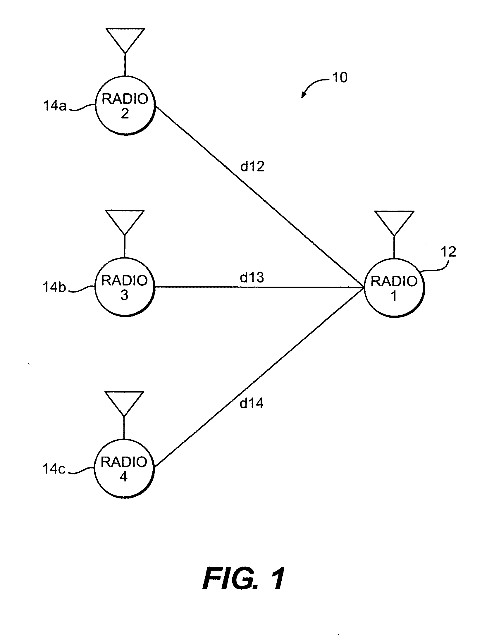
[0037]Depicted in FIG. 1 is an exemplary RF ranging system, designated generally by 10. System 10 includes a mobile radio 12 and at least one other radio, designated generally by 14, which may be fixed (e.g., a stationary radio or cell phone tower) or mobile. RF ranging system 10 may be used to calculate the distance between mobile radio 12 and any one of the other radios, for example radio 14a, and / or may be used to find the location of mobile radio 12 relative to a plurality of other radios, for example, radios 14a, 14b, and 14c, which may be organized into a network.

[0038...


PUM


Abstract

Methods for estimating a distance between an originator and a transponder, methods for calculating a fine time adjustment in a radio, computer-readable storage media containing instructions to configure a processor to perform such methods, originators used in a system for estimating a distance to a transponder, and transponders used in a system for estimating a distance to an originator. The methods utilize fine time adjustments to achieve sub-clock cycle time resolution. The methods may utilize offset master clocks. The methods may utilize a round-trip full-duplex configuration or a round-trip full-duplex configuration. The method produces accurate estimates of the distance between two radios.

Description

BACKGROUND[0001]1. Technical Field[0002]This invention relates to radio frequency ranging systems that provide an estimate of the distance between two radios and / or the relative or absolute position of a radio.[0003]2. Description of Related Art[0004]Radio-frequency (RF) ranging technology provides distance and relative position between objects without the need to take physical measurements. RF ranging systems calculate the distance between two objects based in part on the time a radio signal propagates between those objects. In air, radio signals propagate at a constant rate, roughly equal to the speed of light.[0005]Knowing the absolute position of a sufficient number of objects (such as e.g., cell phone towers fixed relative to the earth), an RF ranging system can be used to determine the absolute position of other objects. An RF ranging system may utilize a signal from the Global Positioning System (GPS) to provide absolute location. In many situations, however, GPS signals are ...

Claims


Application Information

Patent Timeline
Patent Type & Authority Applications(United States)
IPC IPC(8): G01S1/24
CPCG01S13/325G01S13/878G01S13/84
Inventor FRETENBURG, RUSSELL ALANLEUNG, HENRY HON-YOUPYNER, DEREK JOHNFARNSWORTH, BRADLEY DAVIDTAYLOR, JR., DAVID W.A.
Owner ENSCO INC
Learn More