Removable wirelessly-chargeable light-emitting device

a wireless charging and light-emitting device technology, applied in semiconductor devices for light sources, light and heating apparatus, planar light sources, etc., can solve the problems of mounting a light-emitting element, limiting the spatial range of use, and undesired constraints to both use and configuration

Inactive Publication Date: 2011-09-15
WINHARBOR TECH CO LTD
View PDF18 Cites 250 Cited by
  • Summary
  • Abstract
  • Description
  • Claims
  • Application Information

AI Technical Summary

Problems solved by technology

However, it has long been considered a difficult to mount a light-emitting element to these articles, thereby imposing undesired constraints to both the use and the configuration thereof.
This limits the spatial range of usage and reduces the convenience of use.

Method used


Image

  • Removable wirelessly-chargeable light-emitting device
  • Removable wirelessly-chargeable light-emitting device
  • Removable wirelessly-chargeable light-emitting device

Examples


first embodiment

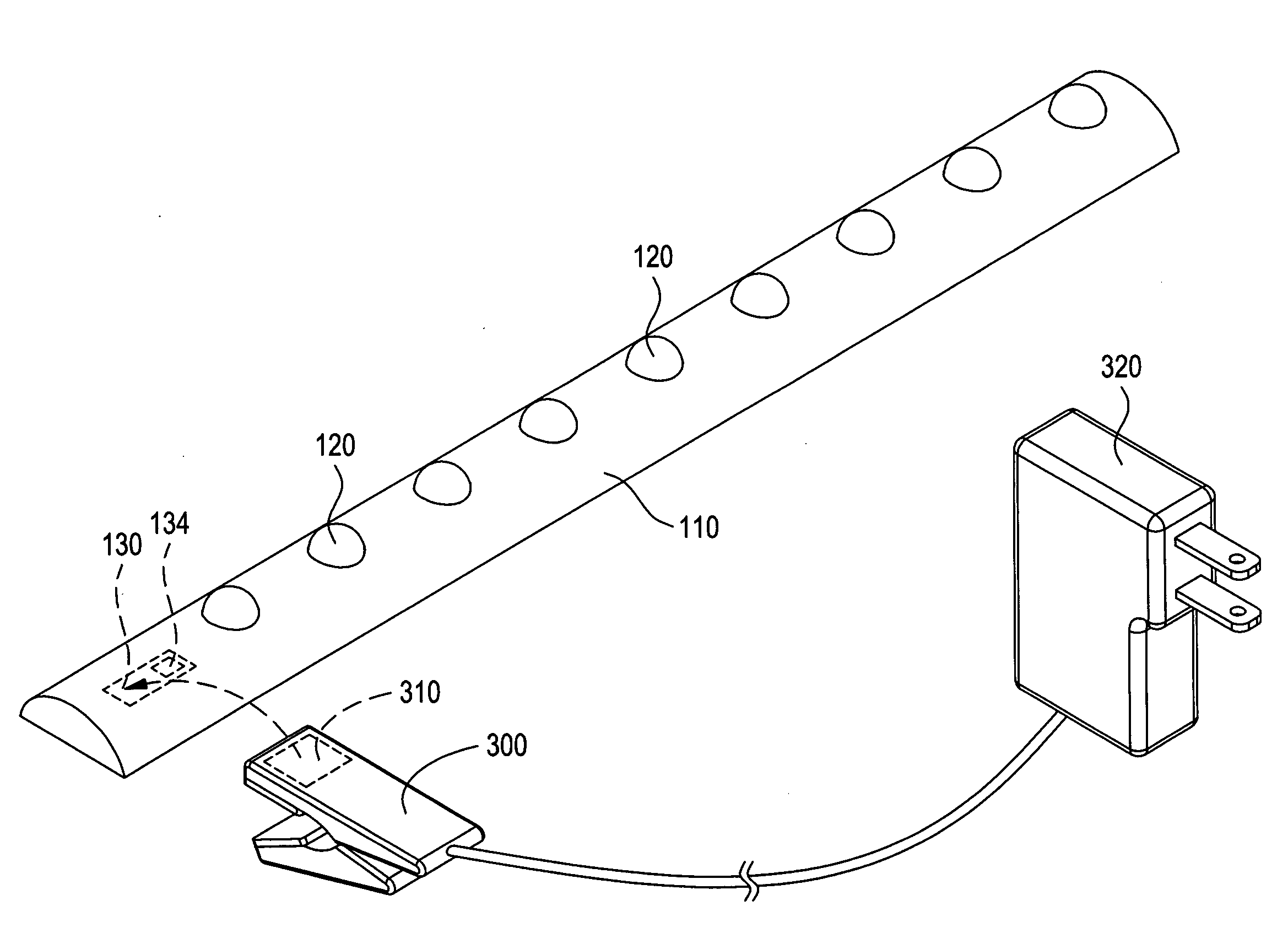
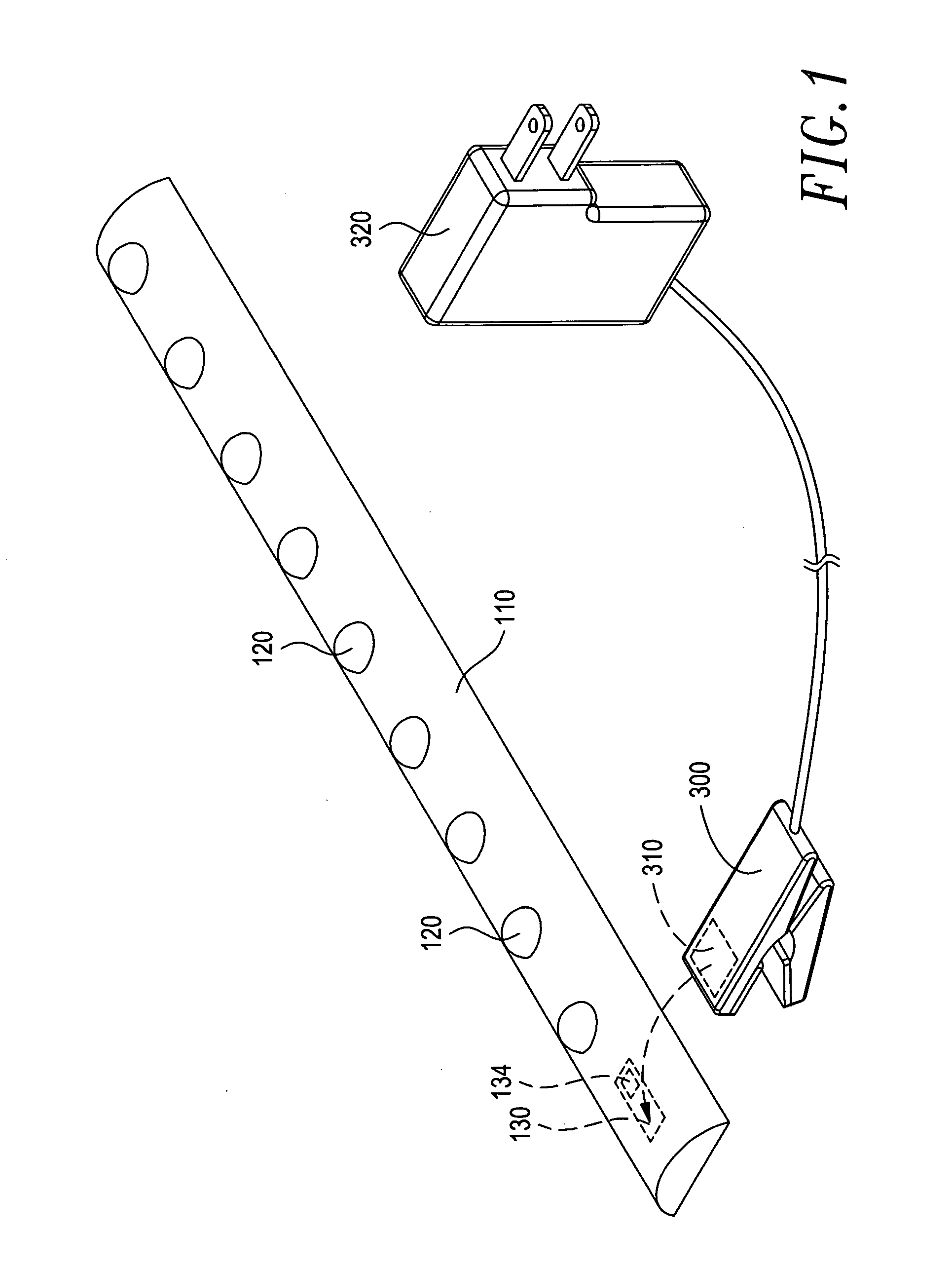
[0020]With reference to the drawings and in particular to FIGS. 1-4, which are respectively a perspective view, a side elevational view, a circuit block diagram of a removable wirelessly-chargeable light-emitting device according to a first embodiment of the present invention and a perspective view illustrating an application of the removable wirelessly-chargeable light-emitting device of the present invention, as shown in the drawings, the removable wirelessly-chargeable light-emitting device of the present invention comprises a body 110, at least one light-emitting element 120, a receiver circuit 130, and at least one fastening member 140 for being mountable to an article 200 and being wirelessly chargeable for energizing the light-emitting element 120 to give off light. The article can be for example garments, pants, shirts, underwear, leather bags, leather belts (waist belts), raincoats, hats, or jackets, but not limited thereto. A charging device 300 is coupled to the article 2...

second embodiment

[0027]Referring to FIGS. 5-7, which are respectively a perspective view, a side elevational view, and a circuit block diagram of a removable wirelessly-chargeable light-emitting device according to a second embodiment of the present invention, the light-emitting device of this embodiment and the manufacturing method thereof are substantially identical to those of the previous embodiment in structure, except a control circuit 150 and a switch 160 are additionally provided. The control circuit 150 and the switch 160 are arranged inside the body 110. The control circuit 150, the switch 160, and the receiver circuit 130 are electrically connected to the light-emitting element 120 for supply of electrical power from the rechargeable battery 134 of the receiver circuit 130 to the light-emitting element 120. The switch 160 performs controls to selectively light on or off the light-emitting element 120 and the control circuit 6 controls the lighting fashion of the light-emitting elements 2 ...

third embodiment

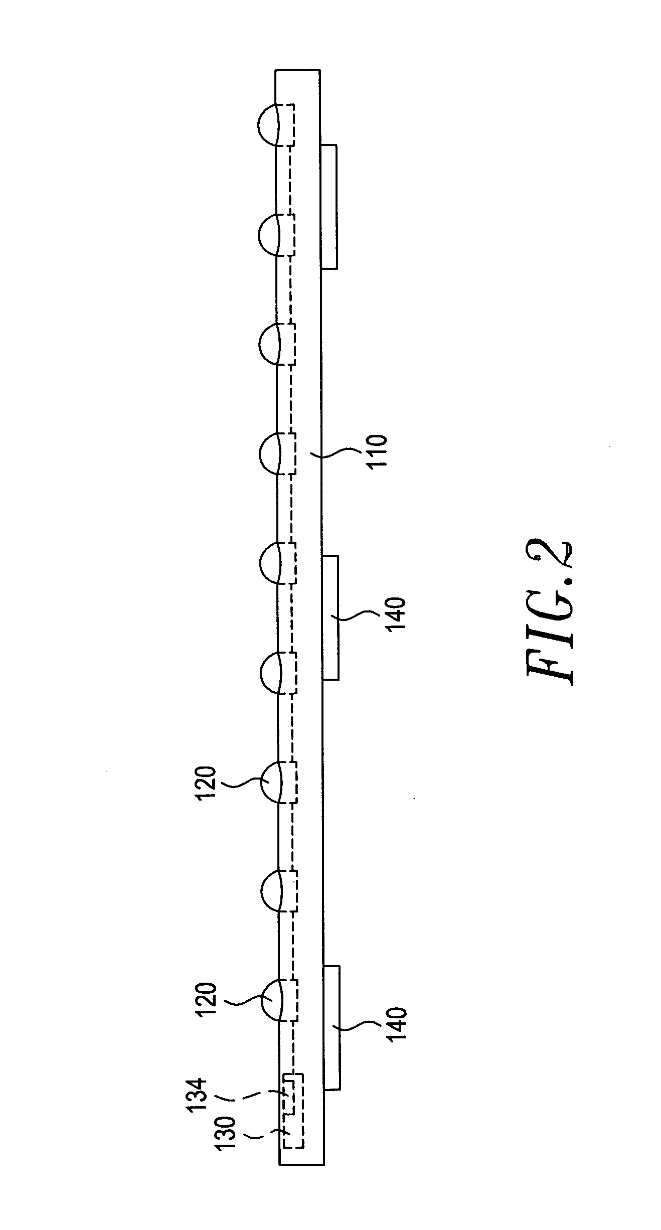
[0028]Referring to FIGS. 8 and 9, which are respectively a perspective view and a side elevational view of a removable wirelessly-chargeable light-emitting device according to a third embodiment of the present invention, the light-emitting device of this embodiment and the manufacturing method thereof are substantially identical to those of the previous embodiments, except a difference in that the fastening member 140 of this embodiment comprises a rivet button. The fastening member 140 is attached to a surface of the body 110 to allow the body 110 to be mounted to an article through the fastening member 140.


PUM


Abstract

The present invention provides a removable wirelessly-chargeable light-emitting device, which includes a body containing therein at least one light-emitting element and a receiver circuit. The body has a surface to which at least one fastening member is mounted, so that direct coupling with an article can be made through the fastening member and wireless charging can be made through the receiver circuit for energizing the light-emitting element to give off light.

Description

FIELD OF THE INVENTION[0001]The present invention relates to a removable wirelessly-chargeable light-emitting device, and in particular to a removable wirelessly-chargeable light-emitting device that is wirelessly chargeable and is mountable to an article of fabric product or leather product to give off light.BACKGROUND OF THE INVENTION[0002]Conventionally, to additionally mount a light-emitting element, such as a light-emitting diode (LED) to a personal item, such as garments, pants, shirts, underwear, leather belts (waist belts), raincoats, hats, or jackets, the only known practice is to mount a light-emitting element to a jacket or a hat to improve nighttime atmosphere, amusing, or aesthetics effect.[0003]Further, these articles are made by applying proper jointing techniques, such as sewing and stitching, bonding (such as ultrasonic bonding), and / or thermal fusion, to joint multiple pieces of fabrics, which can be of different materials, different colors, and different shapes, t...

Claims


Application Information

Patent Timeline
Patent Type & Authority Applications(United States)
IPC IPC(8): F21L4/08
CPCF21L4/08H02J7/025F21Y2105/008F21Y2101/02F21S4/00F21Y2105/00F21Y2115/15F21Y2115/10F21Y2103/10H02J7/0042H02J50/005H02J50/12
Inventor YEH, MING-HSIANG
Owner WINHARBOR TECH CO LTD
Why Eureka
Try Eureka