Ultrasonic machining module

Active Publication Date: 2011-09-15
EDISON IND INNOVATION
View PDF32 Cites 50 Cited by
  • Summary
  • Abstract
  • Description
  • Claims
  • Application Information

AI Technical Summary

Problems solved by technology

More specifically, very advanced materials such as armor plates and composites are notoriously difficult to machine with standard methods.
High-speed systems and ultra-hard tool bits are used for materials such as these, but provide only a marginal increase in tool life and productivity.
However, these processes are high in capital cost, limited in application, and differ too much to be used in standard

Method used


Image

  • Ultrasonic machining module
  • Ultrasonic machining module
  • Ultrasonic machining module

Examples


Embodiment Construction

[0018]Exemplary embodiments of the present invention are now described with reference to the Figures. Reference numerals are used throughout the detailed description to refer to the various elements and structures. Although the following detailed description contains many specifics for the purposes of illustration, a person of ordinary skill in the art will appreciate that many variations and alterations to the following details are within the scope of the invention. Accordingly, the following embodiments of the invention are set forth without any loss of generality to, and without imposing limitations upon, the claimed invention.

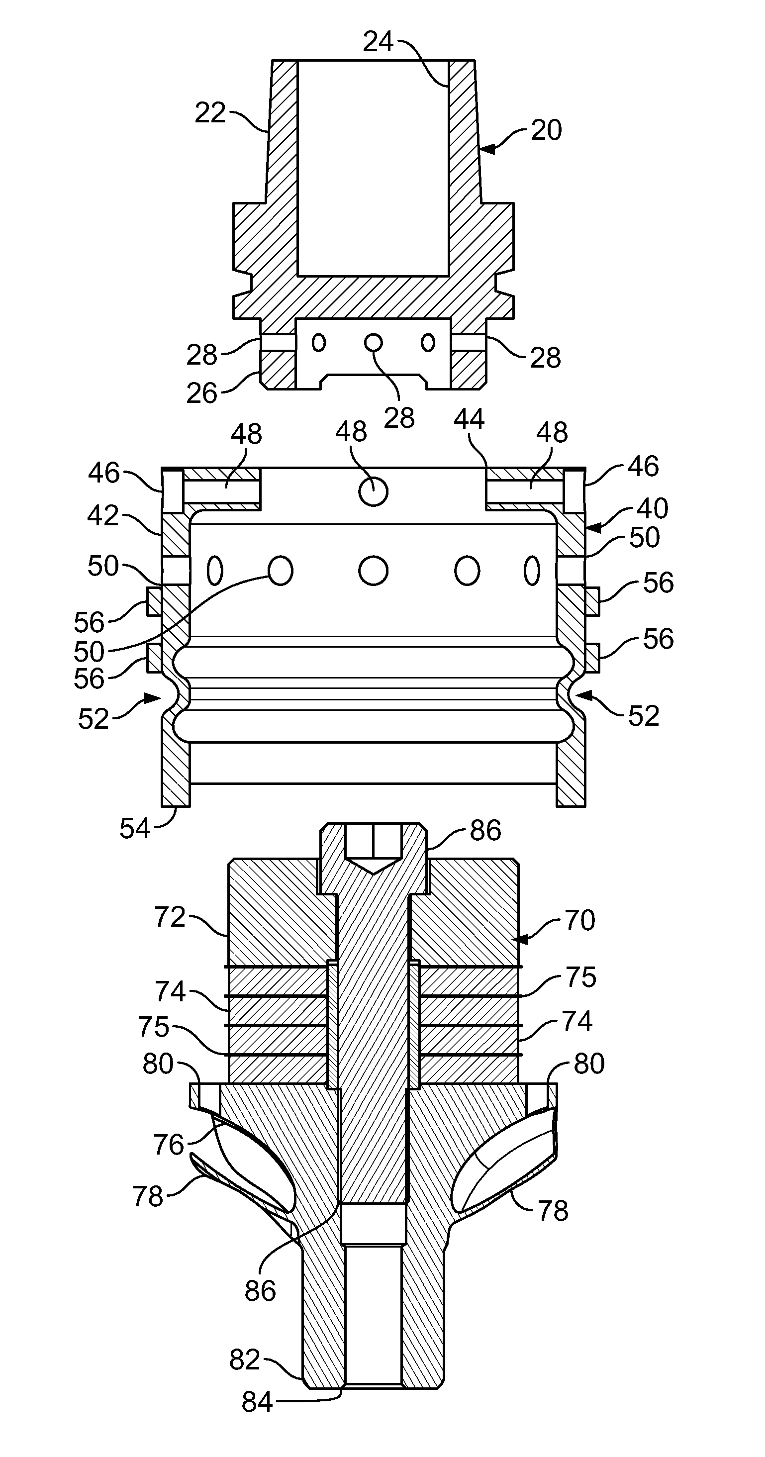
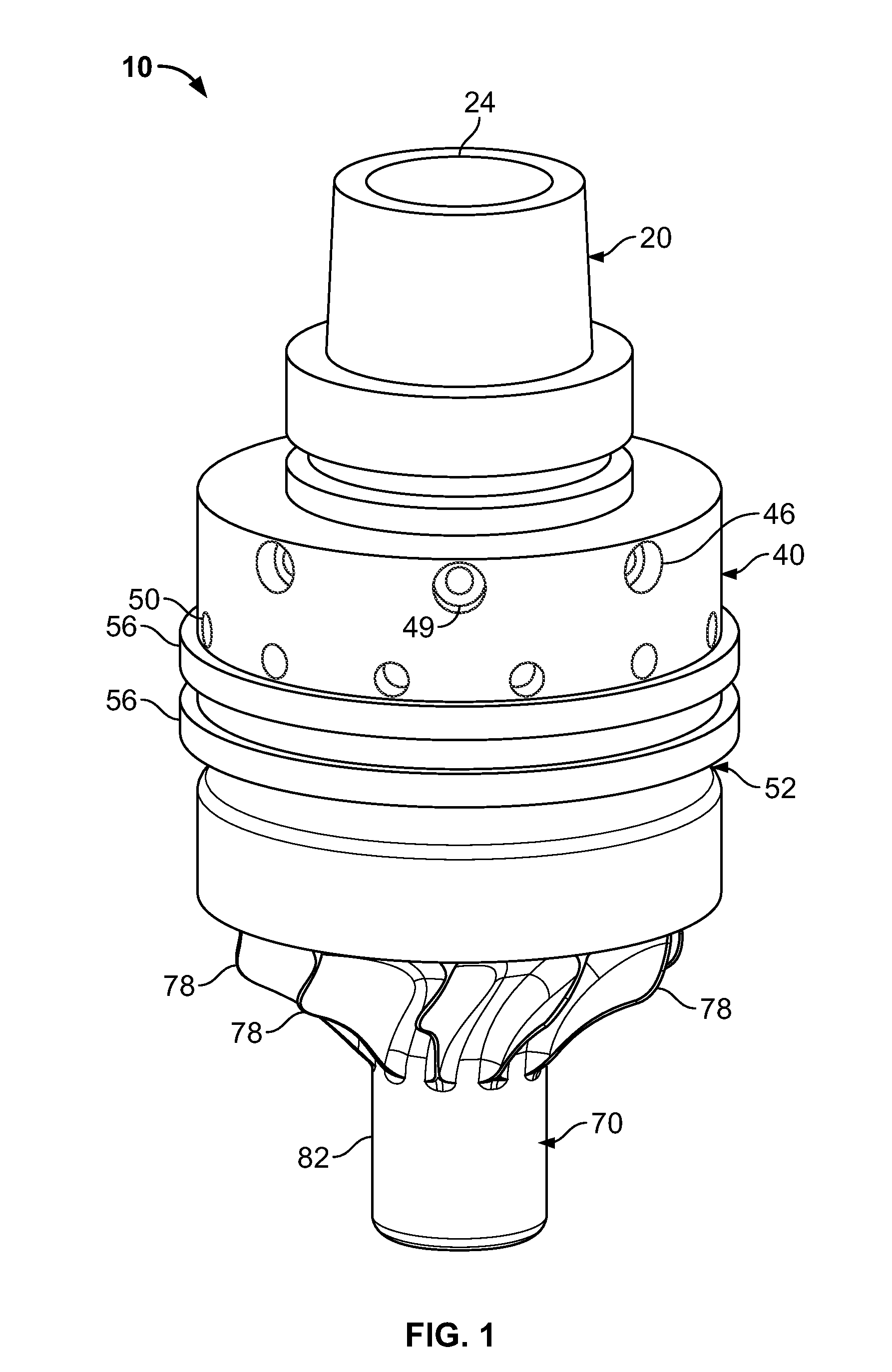
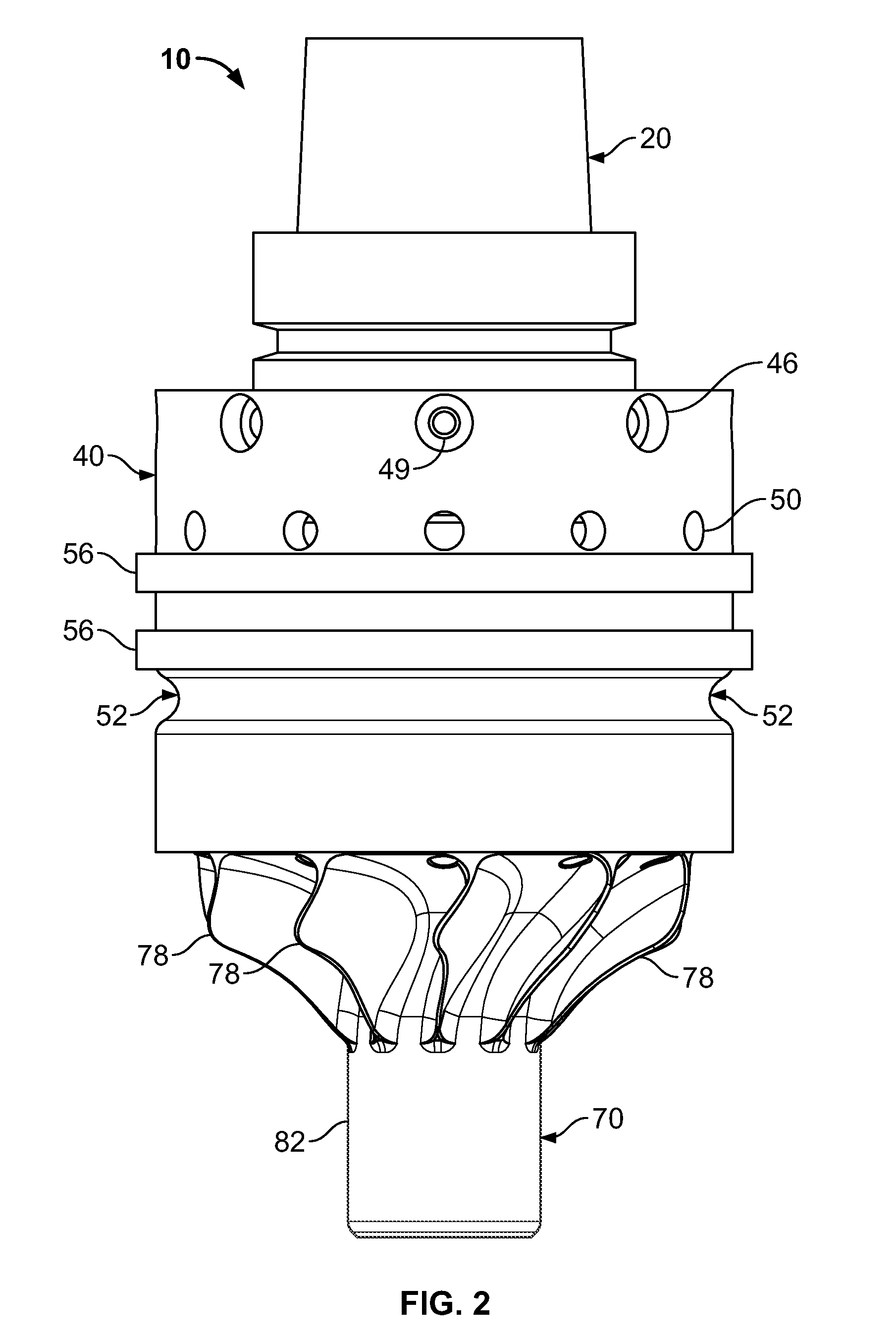
[0019]The present invention provides a detachable and / or replaceable machining module capable of applying ultrasonic energy to machining tools while operating within existing machining systems such as, for example, a Haas Machining Center. This machining module can be adapted to fit existing machinery and, in exemplary embodiments, utilizes a standard CAT / H...


PUM

PropertyMeasurementUnit
Massaaaaaaaaaa

Abstract

A device for use in a machining system, including an ultrasonic transducer, wherein the ultrasonic transducer is adapted to receive a tool bit; a housing adapted to be both compatible with the machining system and to receive the ultrasonic transducer, wherein the housing is operative to isolate all radial and other vibrations generated by the ultrasonic transducer except the axial vibrations transmitted to the tool bit; and a tool holder, wherein the tool holder and the top portion of the housing are mechanically coupled to one another.

Description

CROSS-REFERENCE TO RELATED APPLICATIONS[0001]This patent application claims the benefit of U.S. Provisional Patent Application Ser. No. 61 / 312,738 filed on Mar. 11, 2010 and entitled “Accessory Module for Applying Ultrasonic Energy to Machining Tools,” the disclosure of which is hereby incorporated by reference herein in its entirety and made part of the present U.S. utility patent application for all purposes.BACKGROUND OF THE INVENTION[0002]The described invention related generally to systems for machining materials and more specifically to a system for machining materials into which an ultrasonic machining module has been incorporated, wherein the ultrasonic machining module is compatible with a variety of machining processes.[0003]Machining, which is a collective term for drilling, milling, reaming, tapping, and turning, is an enabling technology that impacts virtually all aspects of manufacturing in the United States and elsewhere. With regard to a specific example, a milling m...

Claims


Application Information

Patent Timeline
IPC IPC(8): B23B43/00
CPCB23B29/125B23B31/02B23B37/00B23B2240/28B23B2250/16Y10T408/45B23B2270/10B23B2270/56B23Q1/0009Y10S408/70Y10T408/23B23B2260/108B23B31/083B23B2231/24B23B2250/12
Inventor SHORT, MATTHEW A.
Owner EDISON IND INNOVATION
Why Eureka
Try Eureka