Motorized spindle

An electric spindle and shaft core technology, applied in the direction of grinding spindles, large fixed members, metal processing machinery parts, etc., can solve problems such as reducing cutting force, and achieve the effect of reducing cutting force, easy removal, and improving service life

Active Publication Date: 2015-03-25
GUANGZHOU HAOZHI ELECTROMECHANICAL
View PDF15 Cites 15 Cited by
  • Summary
  • Abstract
  • Description
  • Claims
  • Application Information

AI Technical Summary

Problems solved by technology

[0003] In view of the deficiencies in the prior art, the purpose of the present invention is to provide an electric spindle, which can not only drive the cutter head to rotate at high speed when ...

Method used


Image

  • Motorized spindle
  • Motorized spindle

Examples


Embodiment Construction

[0024] Below, in conjunction with accompanying drawing and specific embodiment, the present invention is described further:

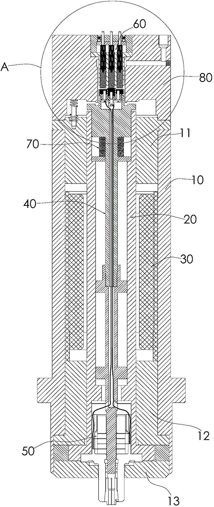
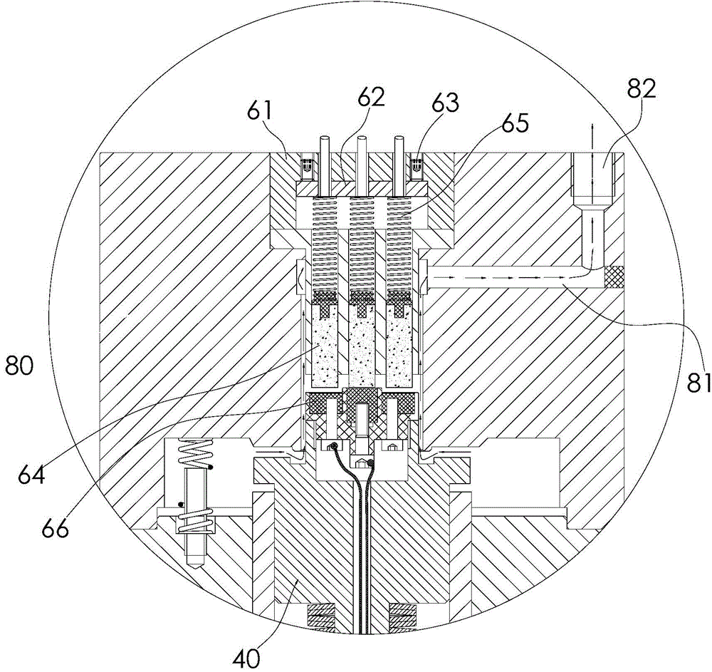
[0025] see figure 1 , 2 As shown, the electric spindle of the present invention includes a fuselage component, a shaft core 20, a motor 30, a pull rod 40, a disc spring 70, an ultrasonic vibrator 50, and a power supply component 60, wherein the shaft core 20 is connected inside the fuselage component and connected with The fuselage assembly pivotally cooperates, and the motor 30 is installed in the fuselage assembly to drive the shaft core 20 to rotate around its own central axis relative to the fuselage assembly. The pull rod 40 is connected inside the shaft core 20, and the pull rod 40 and the shaft core 20 clearance fit and can extend the axial movement of the shaft core 20, the lower end of the pull rod 40 passes through the shaft core 20 to connect with the tool, and the disc spring 70 is installed between the shaft shoulder on the pull rod 40 and...


PUM


Abstract

The invention provides a motorized spindle comprising a machine body assembly, a central spindle body, a motor, a pull rod, an elastic component, an ultrasonic vibrator and a power supply assembly. The central spindle body is connected into the machine body assembly in a penetrating mode and is matched with the machine body assembly in a pivoting mode. The motor is installed in the machine body assembly and is used for driving the central spindle body to rotate. The pull rod is connected into the central spindle body in a penetrating mode and can move in the axial direction of the central spindle body. The lower end of the pull rod is connected with a cutter. The elastic component is installed between the central spindle body and the pull rod and is used for jacking the pull rod upwards. The ultrasonic vibrator is fixed to the lower end of the central spindle body. A clamping portion which clamps the cutter when the pull rod tends to pull the cutter to move upwards is arranged in the ultrasonic vibrator. The power supply assembly is used for providing electricity for the ultrasonic vibrator. The central spindle body of the motorized spindle body can conduct axially high-frequency vibration during high-speed rotation, ultrasonic machining is conducted on the machined surface of a workpiece, cutting force is reduced, the defects of burning damage, deformation, residual stress and the like are effectively overcome, the service life of the cutter is prolonged, and hard brittle materials can be machined.

Description

technical field [0001] The invention relates to the technical field of machining, in particular to an electric spindle. Background technique [0002] Most of the current electric spindles are used for grinding, boring, drilling and other processing of metal workpieces. During processing, the shaft core of the electric spindle drives the cutter head of the tool to rotate at a high speed on the processing surface of the workpiece. The existing The cutter head of the tool driven by the electric spindle only rotates in a plane. When removing the allowance of the workpiece processing surface, the rotating cutter head is hindered by the allowance of the workpiece processing surface, so a large cutting force must be paid to overcome the machining surface allowance of the workpiece. At the same time, when the existing electric spindle is processing the workpiece, defects such as burns, deformation and residual stress will usually be formed on the processing surface of the workpiece....

Claims


Application Information

Patent Timeline
IPC IPC(8): B23B19/02
CPCB23Q1/70B24B41/044
Inventor 汤秀清单杰
Owner GUANGZHOU HAOZHI ELECTROMECHANICAL
Why Eureka
Try Eureka