Ultrasonic machining assembly for use with portable devices

a technology of ultrasonic machining and portable devices, which is applied in the direction of mechanical vibration separation, manufacturing tools, mechanical machines/dredgers, etc., can solve the problems of high capital cost of processes, limited application, and notoriously difficult to machine advanced materials such as armor plates and composites with standard methods

Active Publication Date: 2011-11-03
EDISON IND INNOVATION
View PDF41 Cites 15 Cited by
  • Summary
  • Abstract
  • Description
  • Claims
  • Application Information

AI Technical Summary

Problems solved by technology

More specifically, very advanced materials such as armor plates and composites are notoriously difficult to machine with standard methods.
High-speed systems and ultra-hard tool bits are used for materials such as these, but provide only a marginal increase in tool life and productivity.
However, these processes are high in capital cost, limited in application, and differ too much to be used in standard machine shops.
Also, their application is limited to certain types of cuts in materials.
Although the use of ultrasonics with modern machining systems provides significant and numerous benefits, there are certain technical challenges involved, not the least of which is the incorporation of ultrasonic energy into machining systems that were not originally designed to accommodate this type of energy output.

Method used


Image

  • Ultrasonic machining assembly for use with portable devices
  • Ultrasonic machining assembly for use with portable devices
  • Ultrasonic machining assembly for use with portable devices

Examples


Embodiment Construction

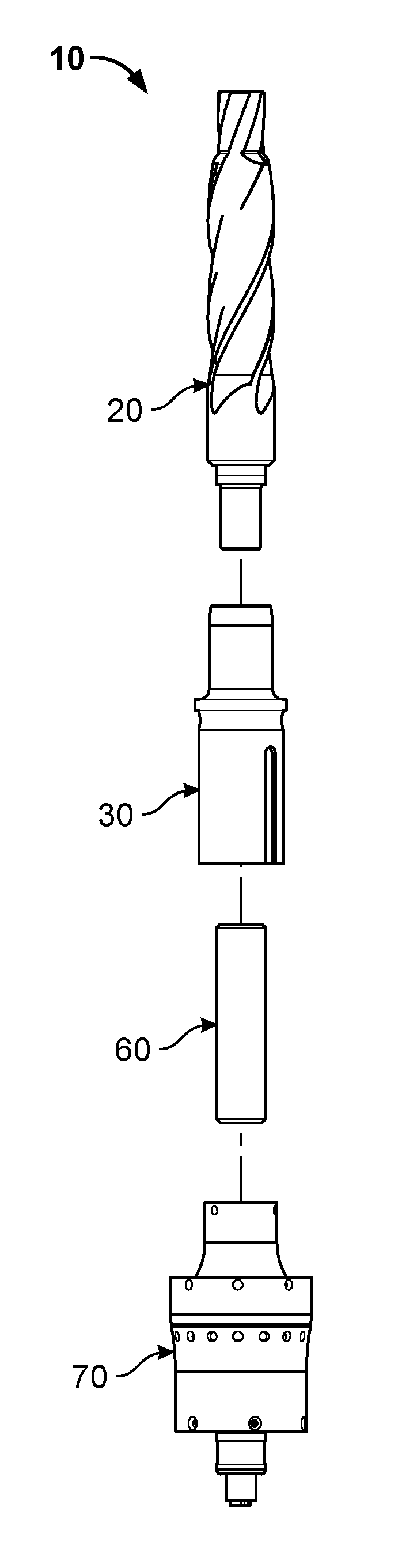
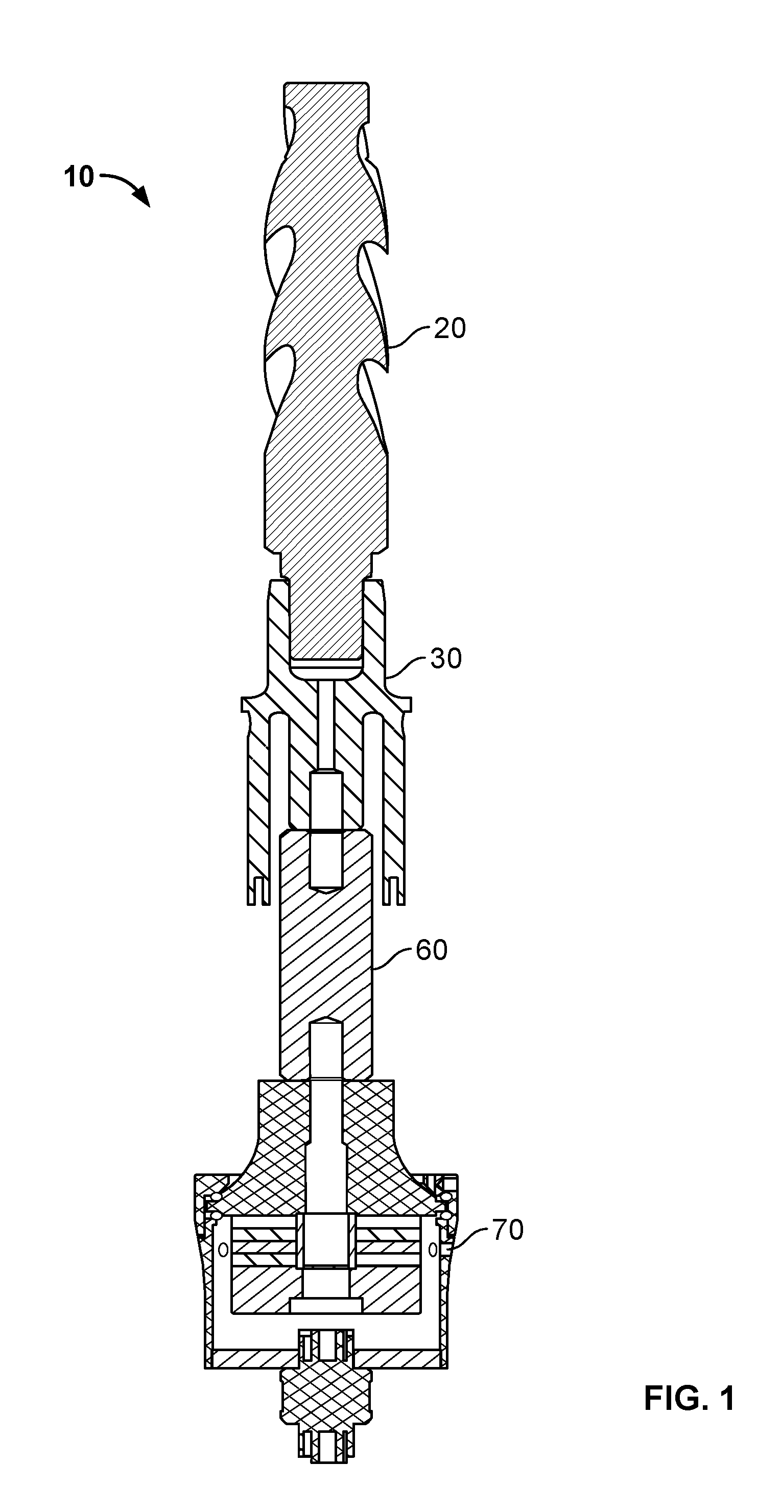
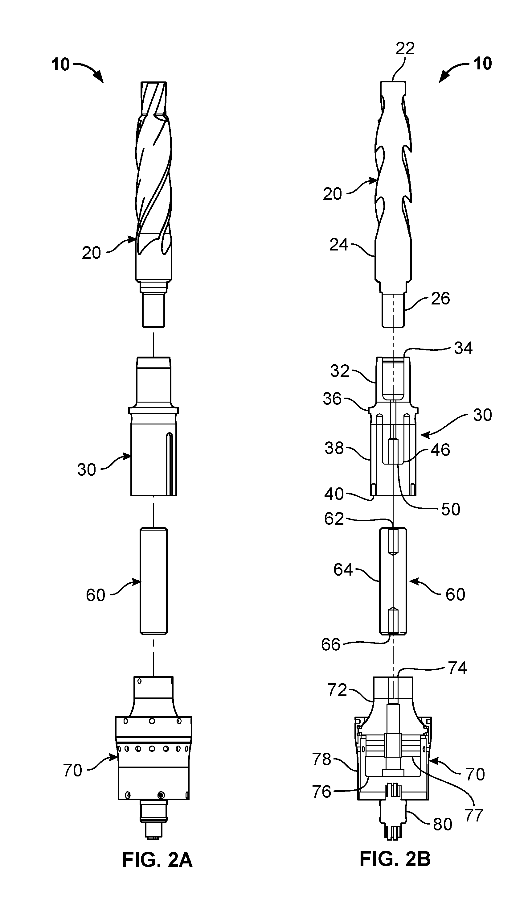
[0017]One or more exemplary embodiments of the present invention are now described with reference to the Figures. Although the following detailed description contains many specifics for purposes of illustration, a person of ordinary skill in the art will appreciate that many variations and alterations to the following details are within the scope of the invention. Accordingly, the following embodiments of the invention are set forth without any loss of generality to, and without imposing limitations upon, the claimed invention. The present invention permits the integration of high power ultrasonics into conventional machine tools, thereby enhancing current industrial processes. This invention permits the machining industry to effectively harness the benefits of ultrasonic machining through a simplified design that uses common tools such as twist drills, mills, reamers, boring bars, and the like. This is accomplished through the use of a modified acoustic transmission line which acts...


PUM

PropertyMeasurementUnit
torqueaaaaaaaaaa
sizeaaaaaaaaaa
speedaaaaaaaaaa

Abstract

A machining system that includes an ultrasonic machining assembly, wherein the ultrasonic machining assembly further includes a machining tool; a collet adapted to receive the machining tool; and an ultrasonic transducer, wherein the ultrasonic transducer is operative to transmit acoustical vibrations to the machining tool; and a machining apparatus, wherein the machining apparatus is adapted to receive and secure the ultrasonic machining assembly, and wherein the machining apparatus is operative to transmit torque to the machining tool by applying rotary motion to the ultrasonic machining assembly.

Description

CROSS-REFERENCE TO RELATED APPLICATIONS[0001]This patent application claims the benefit of U.S. Provisional Patent Application Ser. No. 61 / 329,355 filed on Apr. 29, 2010 and entitled “Ultrasonic Machining System” and U.S. Provisional Patent Application Ser. No. 61 / 333,483 filed on May 11, 2010 and entitled “Ultrasonic Machining System”, the disclosures of which are hereby incorporated by reference herein in their entirety and made part of the present U.S. utility patent application for all purposes.BACKGROUND OF THE INVENTION[0002]The described invention related generally to systems for machining materials and more specifically to a system for providing both longitudinal and rotary motion to a tool used for machining very hard materials.[0003]Machining, which is a collective term for drilling, milling, reaming, and turning, is an enabling technology that impacts virtually all aspects of manufacturing in the United States and elsewhere. With regard to a specific example, a milling ma...

Claims


Application Information

Patent Timeline
Patent Type & Authority Applications(United States)
IPC IPC(8): B23B47/04B23Q5/04
CPCB23B29/125B23B37/00B23B2270/10Y10T408/675Y10S408/70Y10T408/23Y10T279/17965B23Q5/04B06B1/00B26D7/08
Inventor SHORT, MATTHEW A.
Owner EDISON IND INNOVATION
Why Eureka
Try Eureka