Eyewear with rigid lens support

a technology of rigid support and eyewear, applied in the field of eyewear, can solve the problems of frequent gap between the foam component b, inability to maintain the desired optical characteristics, and uneven wear of the wearer's face, so as to improve ventilation and reduce fogging of the goggle

Active Publication Date: 2011-09-22
OAKLEY INC
View PDF103 Cites 29 Cited by
  • Summary
  • Abstract
  • Description
  • Claims
  • Application Information

AI Technical Summary

Benefits of technology

[0011]A goggle usually comprises an arcuate unitary lens which extends across both of the wearer's right and left eye fields of view. The lens can be supported by a frame, which typically surrounds the lens. The lens and the frame are both configured with a downwardly concave indent or nosepiece opening for receiving the nose. The rear surface of the frame, normally covered with a foam component or other compressible material, is adapted to contact the wearer's face. Further, the elastic strap is connected to the opposing sides or ends of the frame so that the wearer can fit and wear the goggle on their head.
[0031]In accordance with some embodiments, the goggle can comprise at least one port disposed along the periphery of the lens support. The port can provide an airflow passage for introducing air over an interconnecting portion of the goggle for improving ventilation and reducing fogging of the goggle. For example, the port can exhibit Venturi airflow characteristics. In some embodiments, the goggle can comprise a pair of ports disposed at the central portion of the lens support above the lens of the goggle.

Problems solved by technology

However, gaps frequently form between the foam component 16 and the surface of the wearer's face due to the preferential bending of the goggle 10.
However, these desirable optical characteristics are not maintained when the goggle 10 is worn by the user in a loaded position.
As a result, the wearer's nose may be pinched and create discomfort for the wearer.
For example, the lens 20 can exhibit substantial prismatic shift and other optical distortions that tend to tire the eyes of the wearer and reduce the wearer's ability to accurately perceive the position of objects.
These disadvantages may not only make use of the goggle 10 uncomfortable, but can potentially affect the wearer's performance of a given activity.
When fitted on a narrow head 40, the goggle 10 can bend about a central section thereof, thus resulting in deformation of the lens and various significant disadvantages, such as those noted above with regard to FIG. 3.
This uneven fit can reduce the air volume within the goggle in the central section, which may reduce the anti-fogging effectiveness of the goggle 10.
The uneven fit may also cause uneven pressure and discomfort against the head 40 of the wearer.
With regard to FIG. 6, when fitted on a wide head 42, the goggle may again experience bending of the lens 20 (albeit toward a larger radius of curvature, which still results in optical distortion).
Although the gap 66 may be minor, such gapping can be problematic in inclement weather or water-related applications, as may be present in skiing and scuba diving.
In such applications, gapping can cause impaired vision.
Further, the uneven compression of the foam component 16 can create uneven pressure and discomfort against the head 42 of the wearer.
As a result, the wearer can generally experience greater discomfort and fatigue.
Additionally, some embodiments reflect the realization that the orientation of the goggle 10 with respect to the wearer's line of sight may be difficult to precisely adjust.
Thus, the wearer may be at a disadvantage in performing activities in which vision could be enhanced by precisely adjusting the orientation of the lens (such as the “rake” of the lens).
Many prior art goggle designs share the deficiency of allowing preferential bending at a midpoint of the goggle frame as the goggle is tightened on a wearer's head that is narrower than the unstressed lateral edge to edge dimension of the goggle.
Such preferential bending creates an inferior fit, reduced optical quality, and may even cause physical and optical discomfort for the wearer.

Method used


Image

  • Eyewear with rigid lens support
  • Eyewear with rigid lens support
  • Eyewear with rigid lens support

Examples


Embodiment Construction

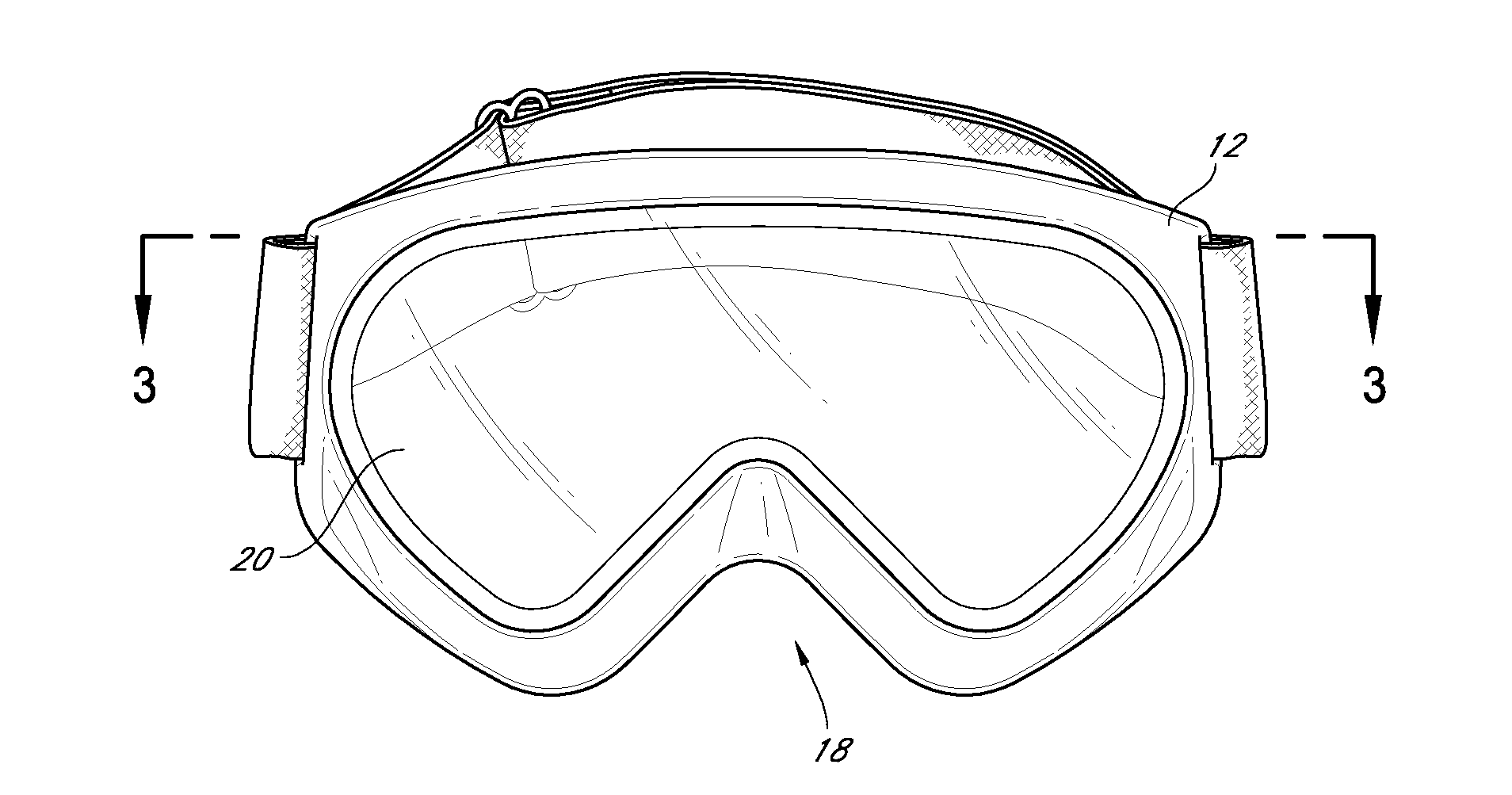
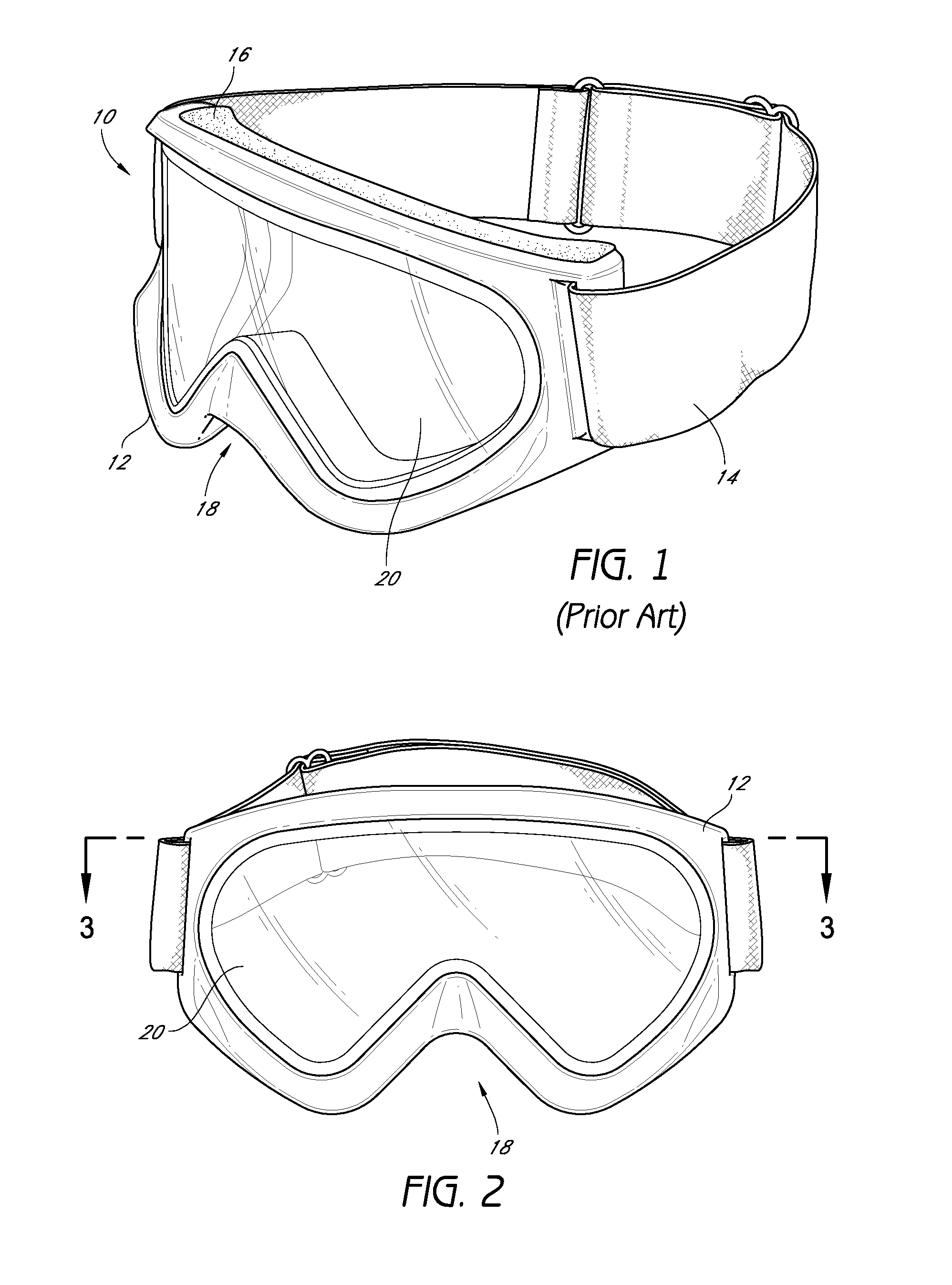
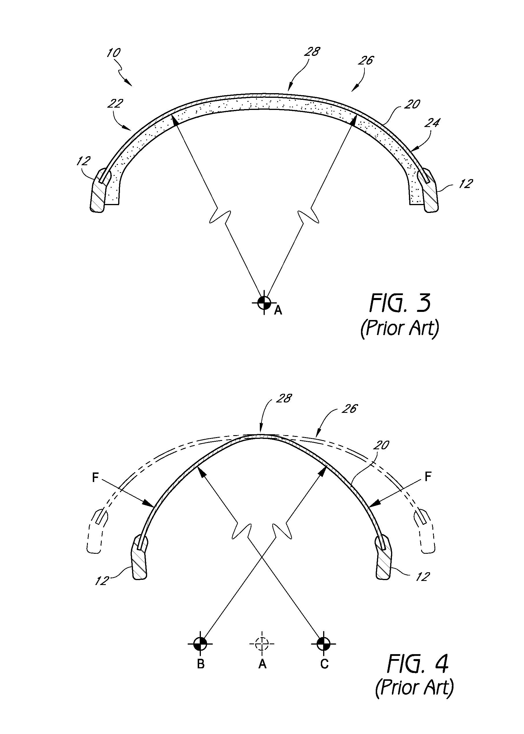
[0113]While the present description sets forth specific details of various embodiments, it will be appreciated that the description is illustrative only and should not be construed in any way as limiting. Additionally, although particular embodiments of the present inventions may be disclosed or shown in the context of unitary or dual lens eyewear systems, such embodiments can be used in both unitary and dual lens eyewear systems. Further, various applications of such embodiments and modifications thereto, which may occur to those who are skilled in the art, are also encompassed by the general concepts described herein. Furthermore, although various embodiments are shown in use with goggles, embodiments can also be used with eyeglasses and other forms of eyewear.

[0114]Some goggle embodiments are provided that overcome many of the disadvantages of the prior art, such as preferential bending, poor comfort, and optical distortion of the lens. Various embodiments are provided that can i...


PUM


Abstract

Eyewear, such as a goggle, is provided that can include an anterior module (such as a lens support) and an interchangeable posterior module (such as a faceplate). The anterior module can be adapted to support at least one lens in a wearer's field of view. The posterior module can be adapted to fit against a contour of the wearer's face and can be selectively interchangeable with the anterior module to modify at least one physical characteristic of the eyewear. In some embodiments, the anterior and posterior modules can be coupled by a suspension assembly in order to allow articulation of the posterior module relative to the anterior module for evenly distributing forces against the wearer's face. Further, the anterior module can be rigid for maintaining the lens in an optically-desirable orientation. Furthermore, the goggle can comprise an interchangeable lens mechanism to facilitate interchanging of lenses in the goggle.

Description

CROSS-REFERENCE TO RELATED APPLICATIONS[0001]This application claims the benefit of U.S. Provisional Application No. 61 / 315,752, filed Mar. 19, 2010 and U.S. Provisional Application No. 61 / 426,222, filed Dec. 22, 2010, the entirety of each of which is incorporated herein by reference.BACKGROUND[0002]1. Field of the Inventions[0003]The present inventions relate generally to eyewear and more specifically to eyeglass and goggle frames, having improved comfort and fit.[0004]2. Description of the Related Art[0005]A wide variety of improvements have been made in recent years in the eyewear field, particularly with respect to eyewear intended for use in active sports, including goggles and sunglasses. These improvements have been incorporated into eyewear and goggles having both dual and unitary lens designs. As a result, modern active sport eyewear is functionally superior to its predecessor eyewear in numerous ways, such as by maximizing interception of peripheral light, reducing optical...

Claims


Application Information

Patent Timeline
Patent Type & Authority Applications(United States)
IPC IPC(8): A61F9/02
CPCA61F9/025A61F9/026G02C11/08A61F9/029A61F9/028
Inventor REYES, CARLOS D.SAYLOR, RYANCASTRO, JAMES NELSONTAZBAZ, ERROLGINTHER, DAVID
Owner OAKLEY INC
Why Eureka
Try Eureka