Oscillator and control method thereof

a technology of oscillator and control method, which is applied in the field of oscillator, can solve problems such as unnecessary power consumption, and achieve the effects of reducing the intensity of first current, reducing power consumption, and steady output frequency

Active Publication Date: 2011-09-22
REALTEK SEMICON CORP
View PDF10 Cites 7 Cited by
  • Summary
  • Abstract
  • Description
  • Claims
  • Application Information

AI Technical Summary

Benefits of technology

[0009]The oscillator and method thereof conceived according to the invention contribute to a decrease of power consumption while maintaining a substantially steady output frequency. The problem observed in prior art is solved by reducing first current intensity after the initiation, which does not interfere with the normal function.

Problems solved by technology

However, the inverter In consistently consumes the relatively large first current during operation, which leads to unnecessary power consumption.

Method used


Image

  • Oscillator and control method thereof
  • Oscillator and control method thereof
  • Oscillator and control method thereof

Examples


Embodiment Construction

[0017]Reference will now be made in detail to the preferred embodiments of the present invention as illustrated in the accompanying drawings.

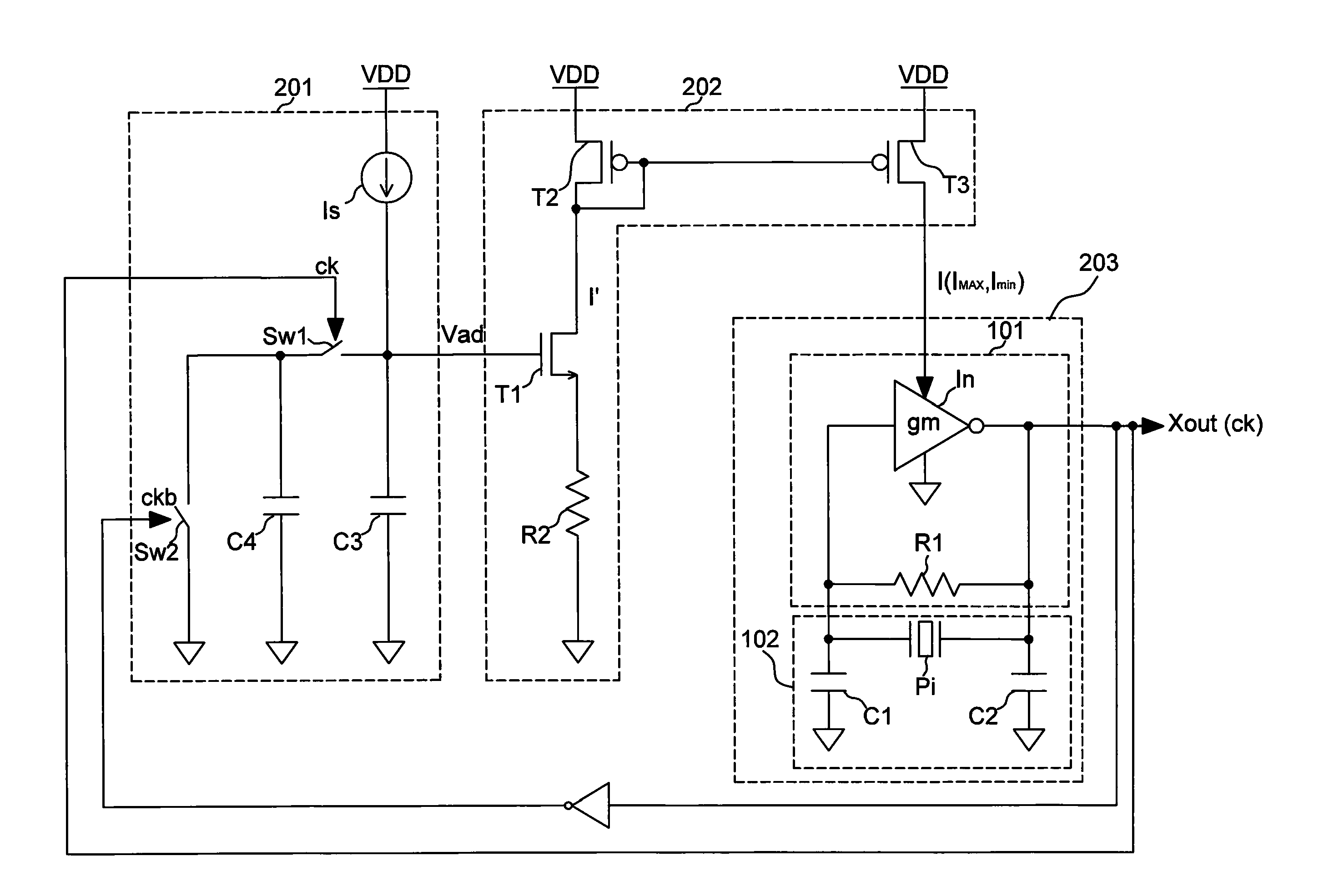
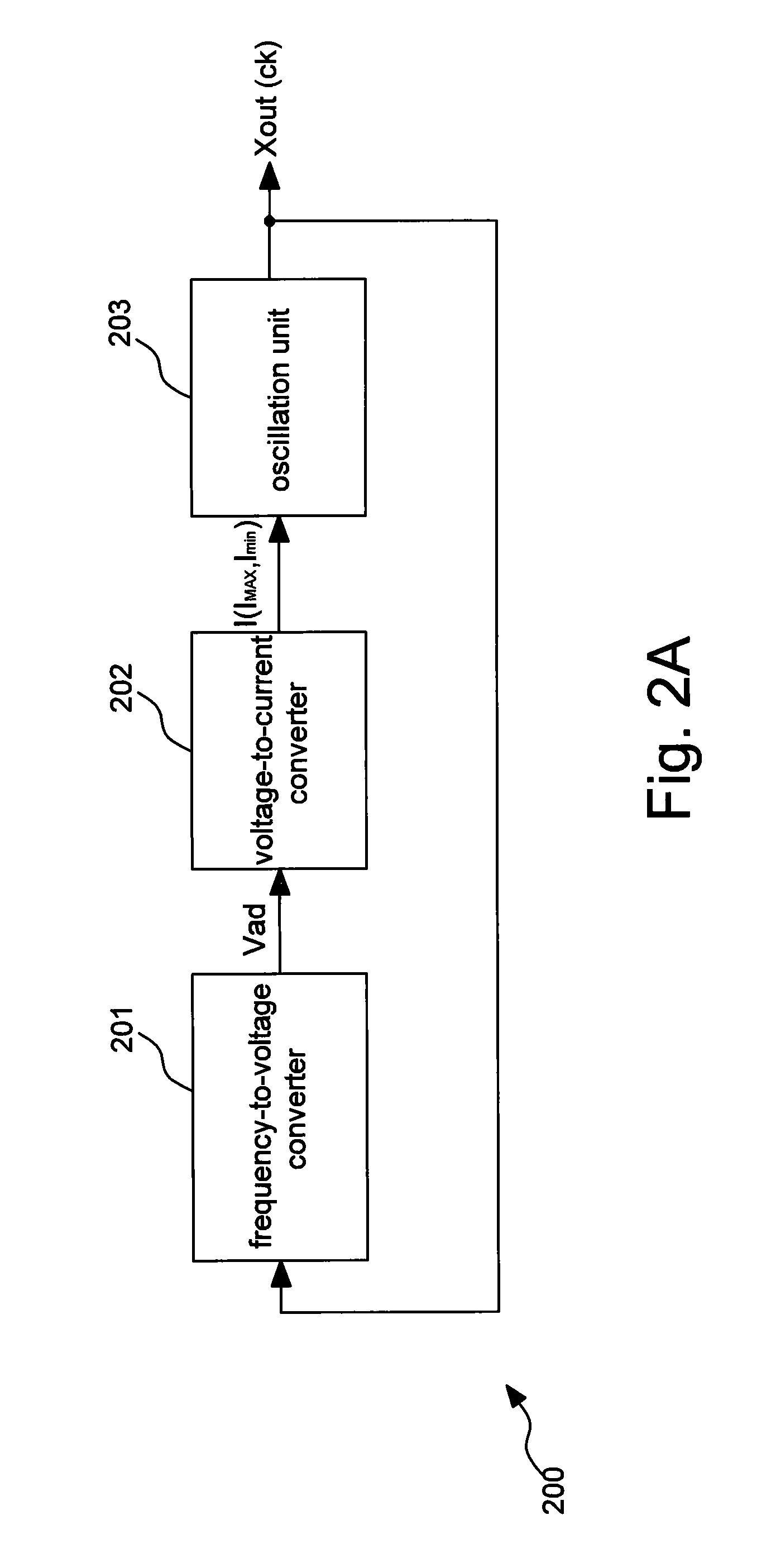
[0018]FIG. 2A is a block diagram illustrating a preferred embodiment of the present invention. The oscillator 200 comprises an oscillation unit 203, a frequency-to-voltage converter 201, and a voltage-to-current converter 202.

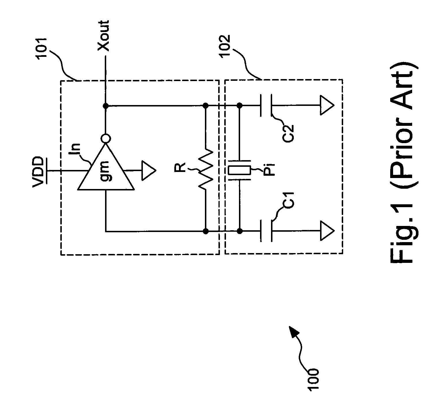
[0019]The oscillation unit 203 receives a current I and outputs an oscillating signal Xout. The oscillation unit 203 in this embodiment may be a replication of the oscillator shown in FIG. 1 or an oscillator of any other kind.

[0020]The frequency-to-voltage converter 201 is coupled to the oscillation unit 203 in order to detect the oscillating signal Xout, which determines a converted voltage Vad.

[0021]The voltage-to-current converter 202 is coupled to the frequency-to-voltage converter 201 in order to generate the current I, which is dependent on the converted voltage Vad.

[0022]It should be noted that the magnitude of the ...


PUM


Abstract

An oscillator and the control method thereof. The oscillator includes an oscillation unit to receive a first current and to generate an oscillating signal according to the first current, a frequency-to-voltage converter to receive the oscillating signal and to generate a converted voltage according to a frequency of the oscillating signal, and a voltage-to-current converter to receive the converted voltage and to generate the first current according to the converted voltage, wherein the first current is modulated from a first value to a second value after the initiation of the oscillation unit.

Description

BACKGROUND OF THE INVENTION[0001](a) Field of the Invention[0002]The invention relates to an oscillator, particularly to an oscillator with power saving features and the method thereof.[0003](b) Description of the Related Art[0004]FIG. 1 is a schematic diagram of a conventional oscillator 100, including an oscillation unit 101 and a crystal circuit 102. The oscillation unit 101 includes an inverter In and a resistor R. The crystal circuit 102 includes a piezoelectric quartz crystal Pi and two capacitors C1, C2.[0005]The oscillation unit 101 generates an oscillating signal Xout by the piezoelectric quartz crystal Pi and capacitors C1, C2. In order to reach a target frequency rapidly during initiation, a large oscillation current (e.g., 3˜6 mA, even larger) is applied to the oscillator 100. During the course of oscillator operation, the oscillation unit 101 and the capacitors C1, C2 generate negative resistance to counteract the equivalent series resistance (ESR) of the piezoelectric ...

Claims


Application Information

Patent Timeline
Patent Type & Authority Applications(United States)
IPC IPC(8): H03K3/01
CPCH03B5/36H03B2200/0082H03K3/0307H03K3/012
Inventor YEH, MING-YUHHUANG, CHEN-CHIHTSAUR, TAY-HER
Owner REALTEK SEMICON CORP
Why Eureka
Try Eureka