Liquid supply apparatus and method, and image recording apparatus

a liquid supply apparatus and liquid supply technology, applied in the direction of water supply installation, operating means/releasing devices of valves, inking apparatus, etc., can solve the problems of liquid ejection defects, operation defects of valves, and the function and performance of liquid supply apparatuses are affected, so as to eliminate the defective operation of the valve arranged in the liquid supply flow channel, the effect of suppressing the liquid inside the flow channel whose operation is affected by the valv

Inactive Publication Date: 2011-09-22
FUJIFILM CORP
View PDF2 Cites 23 Cited by
  • Summary
  • Abstract
  • Description
  • Claims
  • Application Information

AI Technical Summary

Benefits of technology

[0009]The present invention has been contrived in view of these circumstances, an object thereof being to provide a liquid supply apparatus, a liquid supply method and an image recording apparatus whereby the amount of pressure variation in liquid inside a flow channel caused by operation of a valve can be reduced, and operational defects of the valve arranged in the flow channel can be eliminated.

Problems solved by technology

An operational defect may occur in the valve due to variation over time, individual differences, a fault in the drive system, and the like.
If an operational defect occurs in the valve, then the control of opening and closing of the flow channel becomes instable, and the function and performance of the liquid supply apparatus decline.
If the pressure variation occurs in the flow channel that supplies liquid to a liquid ejection head (e.g., an inkjet head), then air bubbles are sucked in through the nozzles of the liquid ejection head, or the liquid overflows from the nozzles, thus giving rise to liquid ejection defects.
Moreover, in Japanese Patent Application Publication Nos. 07-269738 and 2008-196596, determination devices are required to measure the current supplied to the solenoid and to determine the position of the valve body, and therefore the apparatus is large and complicated, thus leading to increased costs.
Consequently, the determination devices become complex, and assembly errors such as wiring errors may occur.

Method used


Image

  • Liquid supply apparatus and method, and image recording apparatus
  • Liquid supply apparatus and method, and image recording apparatus
  • Liquid supply apparatus and method, and image recording apparatus

Examples


first embodiment

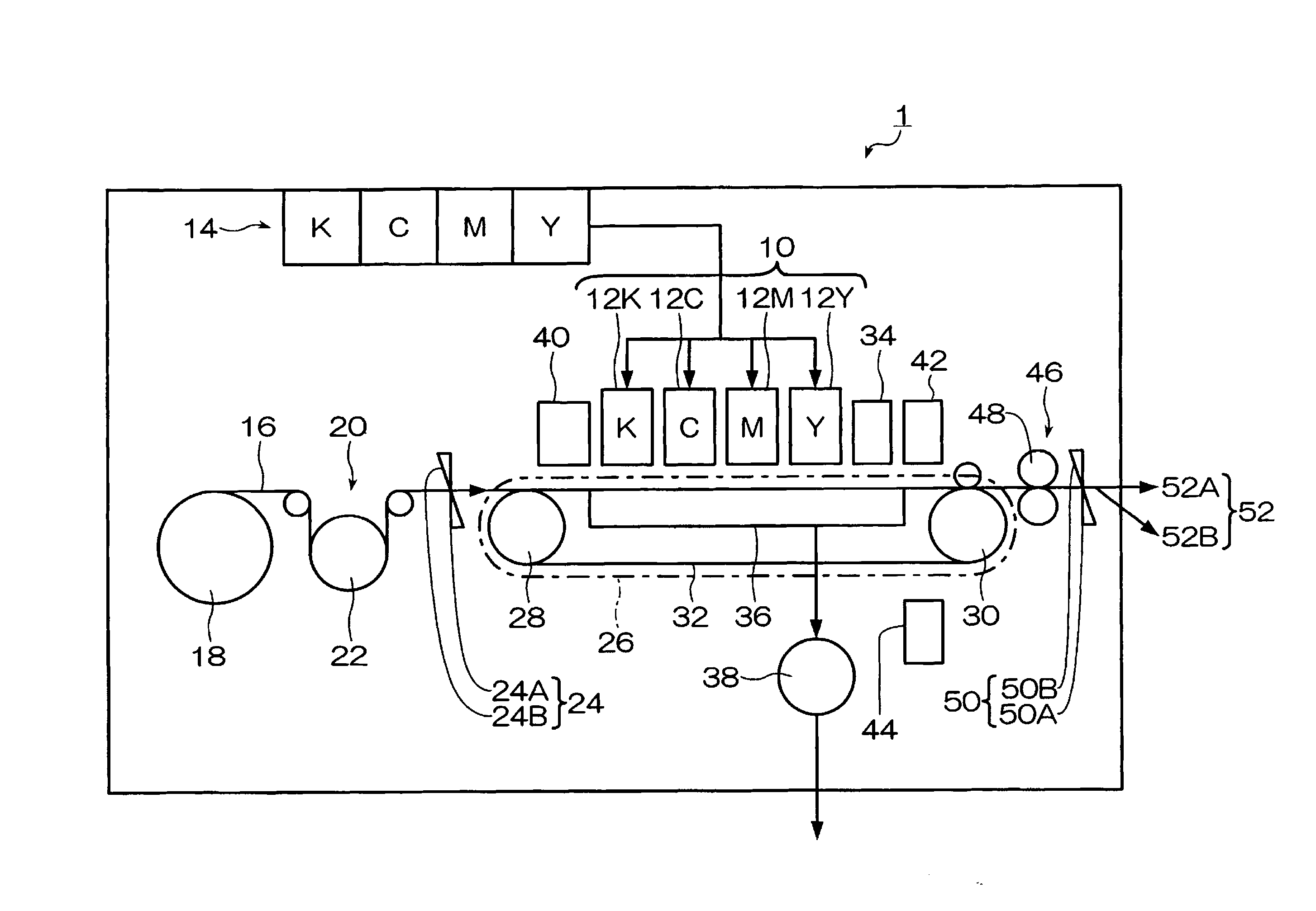
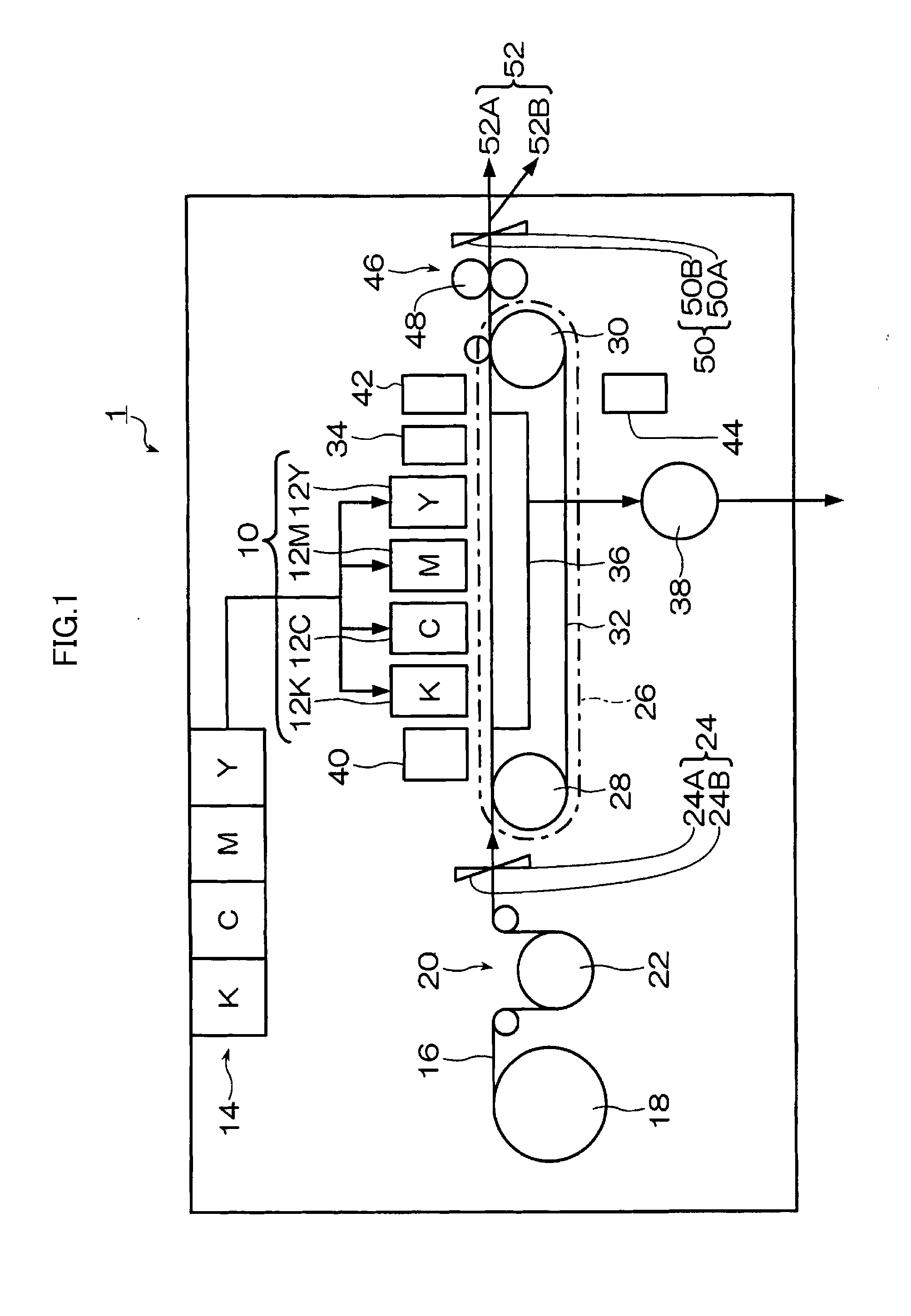
[0039]FIG. 1 is a diagram showing a schematic view of an image recording apparatus or inkjet recording apparatus according to a first embodiment of the present invention.

[0040]As shown in FIG. 1, the image recording apparatus 1 (inkjet recording apparatus) in the present embodiment has a print unit 10 including liquid ejection heads 12K, 12C, 12M and 12Y (hereinafter referred collectively to as the liquid ejection heads 12), and forms a color image by ejecting and depositing droplets of inks of four colors onto a printing surface of recording paper 16 from the print unit 10 on the basis of image data input from a host computer 120 (see FIG. 3).

[0041]Each liquid ejection head 12 is a full-line type liquid ejection head having a length corresponding to the maximum paper width of the recording paper 16, and is arranged in a direction (the main scanning direction (X direction)) that is perpendicular to a paper conveyance direction (sub-scanning direction (Y direction)). The liquid eject...

second embodiment

[0087]Next, a second embodiment of the present invention is described. The description of the composition which is similar to that of the first embodiment described above is omitted here.

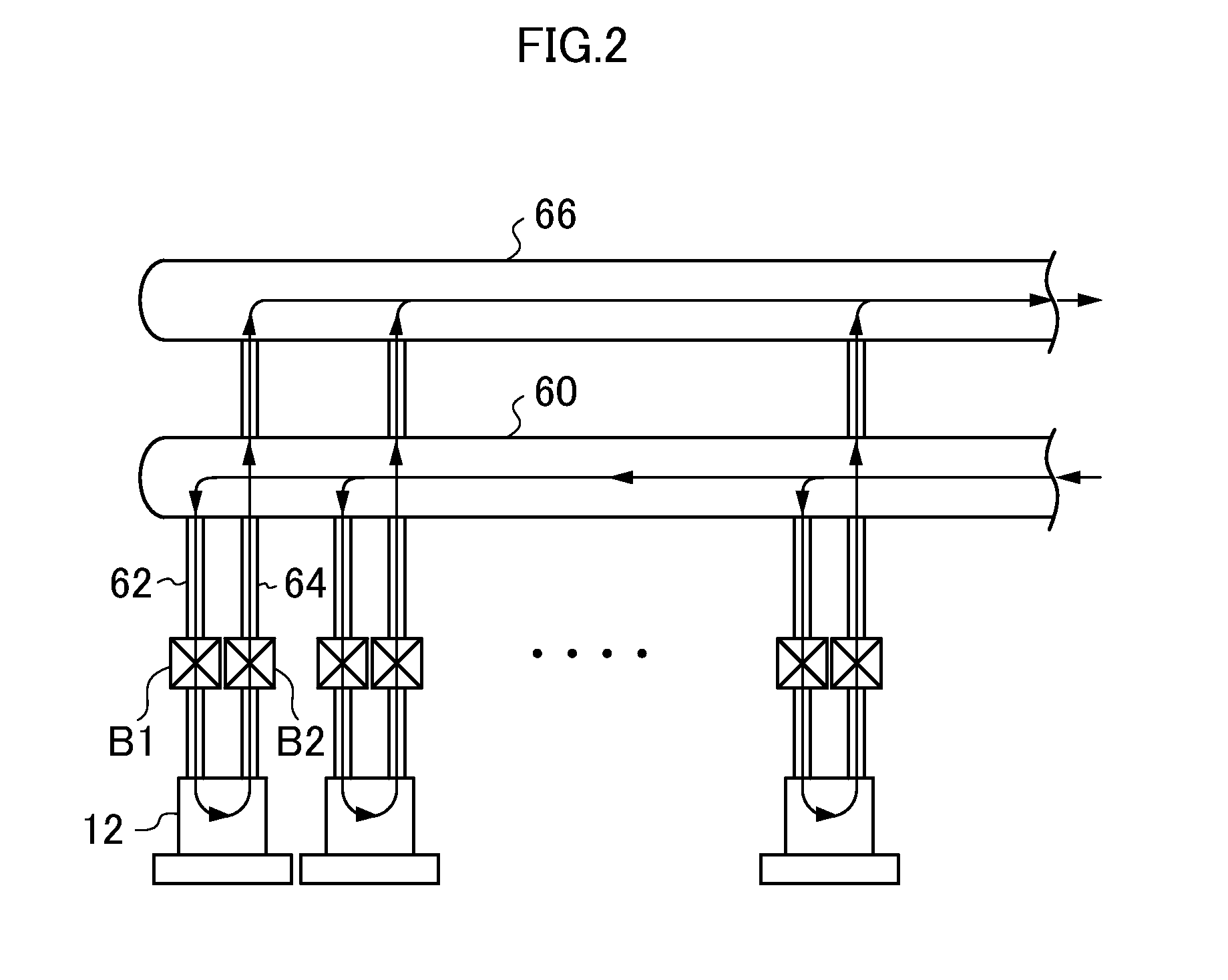
[0088]FIG. 8 is a diagram showing the ink tubes in the second embodiment of the present invention, and FIG. 9 is a block diagram showing a control system of the inkjet recording apparatus 1 in the second embodiment of the present invention.

[0089]As shown in FIG. 8, in the present embodiment, pressure sensors 68 and 70 are arranged respectively on the end portions of the main supply tube 60 and the main return tube 66. The pressure sensors 68 and 70 respectively measure the pressure of the ink inside the main supply tube 60 and the main return tube 66. It is also possible to arrange the pressure sensors 68 and 70 in the distributary supply tube 62 and the tributary return tube 64.

[0090]The pressure sensors 68 and 70 measure the pressure inside the main supply tube 60 and the main return tube 66, at p...


PUM


Abstract

A liquid supply apparatus includes: a liquid supply flow channel which is connected to a liquid ejection head; a valve which is arranged in the liquid supply flow channel and opens and closes in accordance with voltage applied to an actuator of the valve; and a voltage control device which controls the voltage applied to the actuator of the valve, and gradually changes the voltage applied to the actuator of the valve from an initial voltage that is lower than a threshold voltage required for the valve to operate to a final voltage that is higher than the threshold voltage.

Description

BACKGROUND OF THE INVENTION[0001]1. Field of the Invention[0002]The present invention relates to a liquid supply apparatus, a liquid supply method and an image recording apparatus, and more particularly to technology for supplying liquid to a liquid ejection head which ejects liquid to a recording medium.[0003]2. Description of the Related Art[0004]Japanese Patent Application Publication No. 07-269738 discloses an electromagnetic valve driving apparatus which drives an electromagnetic valve having an actuator or a solenoid and a valve body that is driven by the solenoid, in which a current supplied to the solenoid is measured, the measured current value is averaged, and the pulse width is adjusted on the basis of the difference between the average current value and a target current value, in such a manner that the target current is obtained.[0005]Japanese Patent Application Publication No. 2008-196596 discloses determining a position of a valve body when an electromagnetic valve is ...

Claims


Application Information

Patent Timeline
Patent Type & Authority Applications(United States)
IPC IPC(8): B41J29/38F16K31/02
CPCB41J2/14233B41J2/175B41J2/17596B41J2202/12B41J29/393B41J2002/14459B41J2202/05B41J2/18Y10T137/0318
Inventor HOSHINO, SHUHEI
Owner FUJIFILM CORP
Why Eureka
Try Eureka