Medical Radiography In 3D

a medical radiography and 3d technology, applied in the field of medical 3d imaging, can solve the problems of relatively poor recovery and the overall time needed for an imaging procedure like this tend to become quite long, and achieve the effect of long exposure times

Active Publication Date: 2011-09-22
PLANMED OY
View PDF9 Cites 7 Cited by
  • Summary
  • Abstract
  • Description
  • Claims
  • Application Information

AI Technical Summary

Benefits of technology

[0013]The invention makes 3D mammography possible with the existing type of mammography apparatus, i.e. with the same kind of x-ray sources and C-arm and related construction as typically used, by enabling the use of substantially long exposure times even though continuously moving the x-ray source during the imaging procedure. This is made possible by arranging for the breast to follow the movement of the x-ray source during at least one exposure phase of the imaging procedure. As the tomographic angle (the angle between the extreme exposure positions of the x-ray source) used in the imaging process may be of several tens of degrees, to make turning of the breast during a number of exposures possible in practise, a preferable embodiment of the procedural cycle of the invention includes a step of turning the breast back to its previous / initial position during a (each) non-exposure period of the imaging process.

Problems solved by technology

When breast cancer is detected on the basis of symptoms, the illness often has already developed to a stage where the prognosis for recovery is relatively poor.
The overall time needed for an imaging procedure like this tends to become quite long.
With this kind of a mechanical design as a basis, it would be a challenge to be able to come up with a construction that would make the apparatus practical for use in conventional 2D screening mammography as well.

Method used


Image

  • Medical Radiography In 3D
  • Medical Radiography In 3D
  • Medical Radiography In 3D

Examples


Embodiment Construction

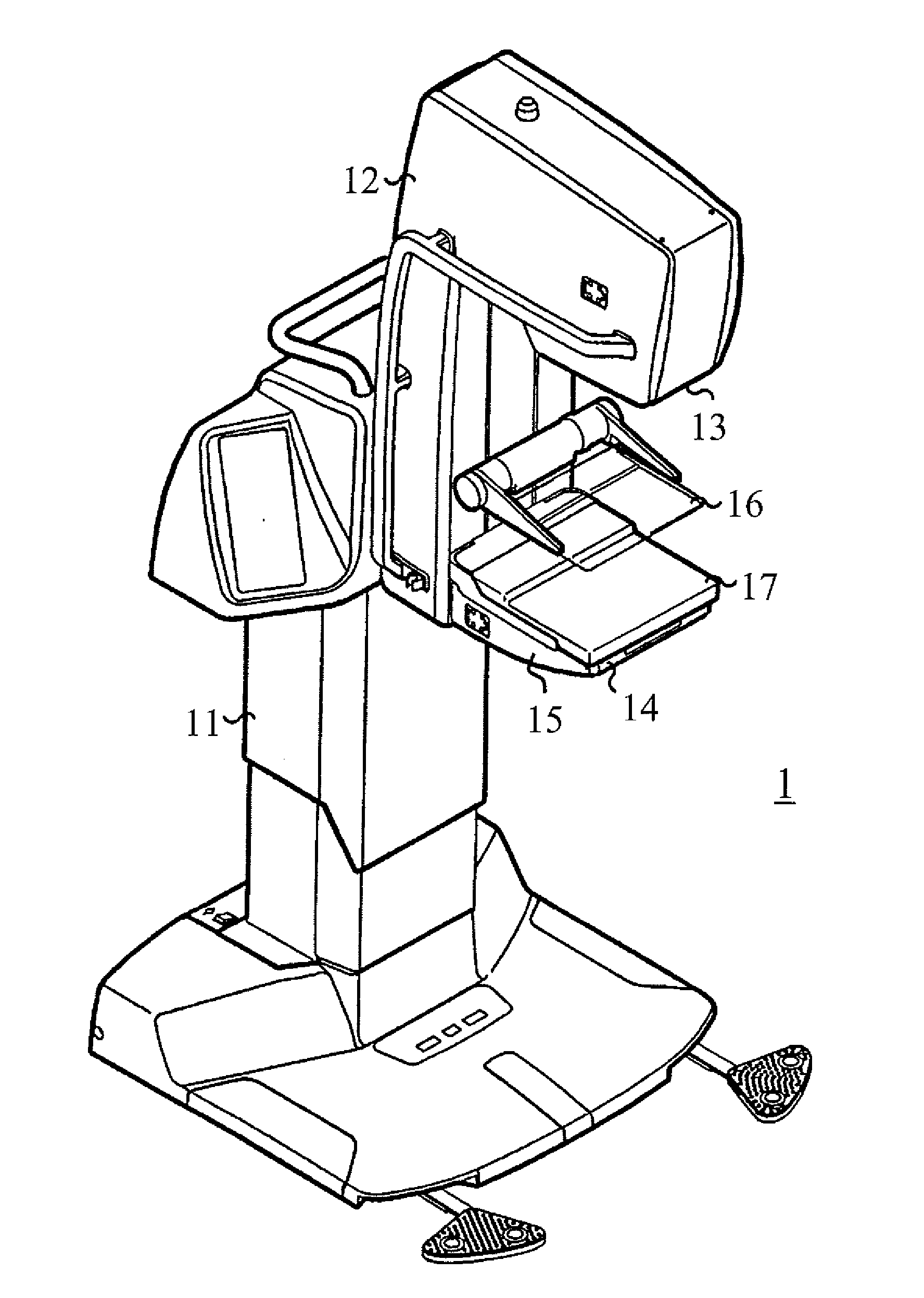
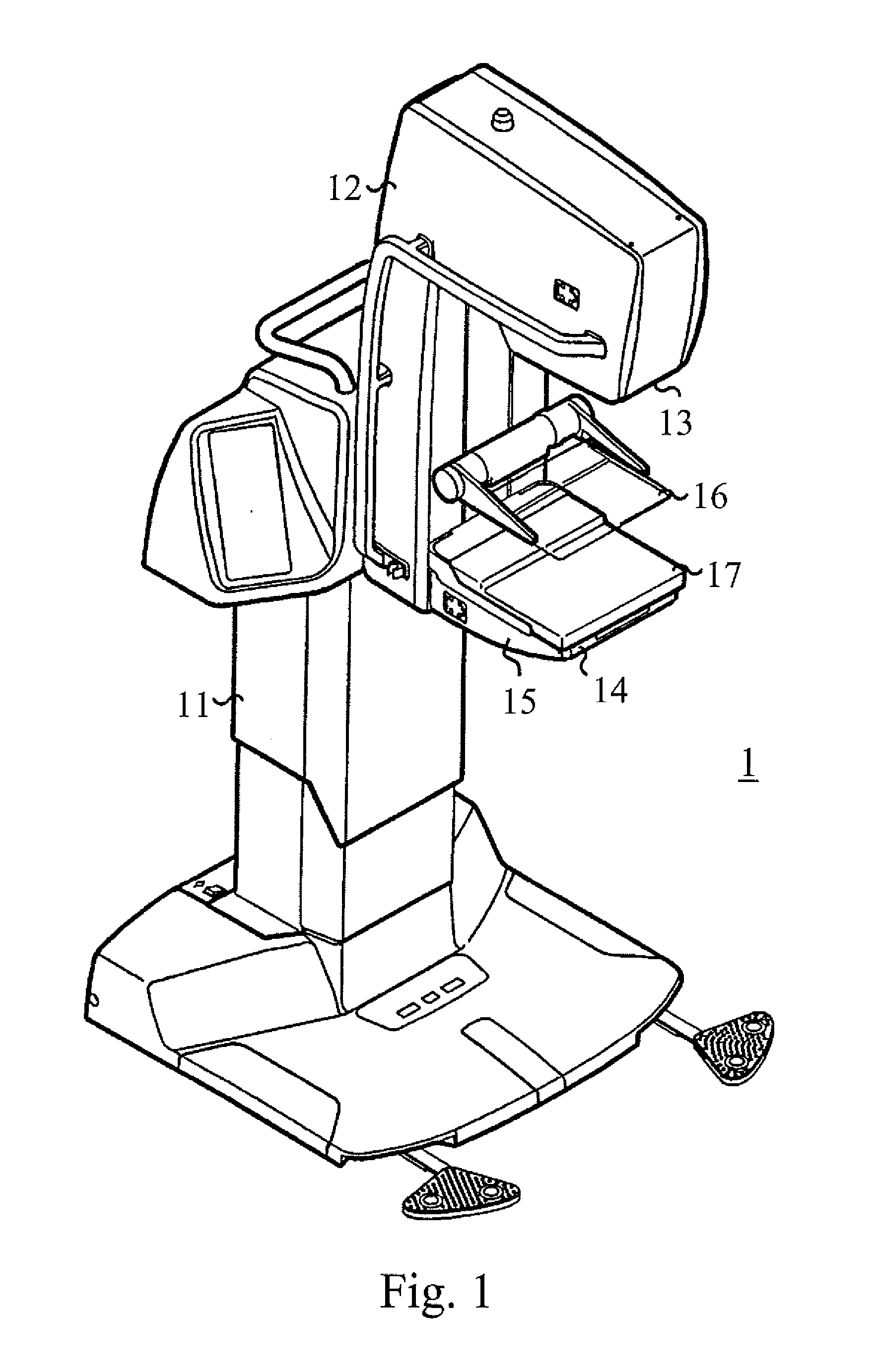
[0021]A typical mammography apparatus 1 as presented in FIG. 1 consists of a body part 11 and a C-arm construction 12 connected to it. Typically, a radiation source 13 and an image data receiving means 15, arranged e.g. inside a so-called lower shelf structure 14, are placed at the opposite ends of the C-arm 12. These depicting means 13, 15, being located inside the cover of the apparatus, are actually not visible in FIG. 1.

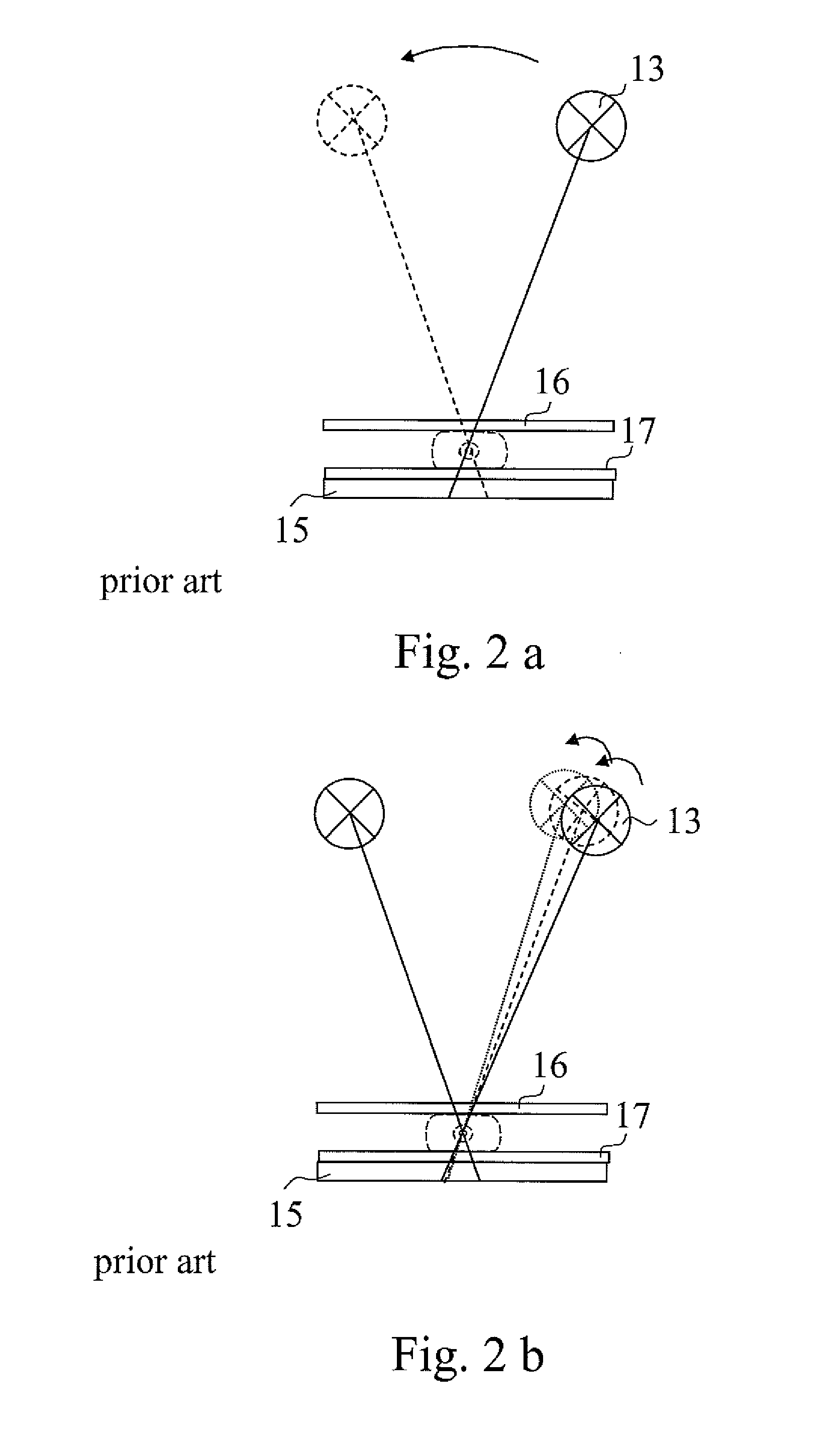
[0022]Further, within the area between the depicting means 13, 15, typically in the proximity of the image data receiving means 15, a means 16, 17 for positioning / locking the object to be imaged within the imaging area has been placed. Nowadays, typically, this kind of an apparatus is motorized such that the C-arm 12 is arranged movable in a vertical direction and rotatable about an axis, typically a physical horizontal axis connecting the C-arm to the body part 11. The positioning / locking means 16, 17 typically consist of an upper compression plate 16 and a lowe...


PUM


Abstract

The present invention relates to medical 3D radiography, such as mammography, in which individual images of an object are taken at different projection angles and a 3D image subsequently synthesized from this image information. According to the invention, the object to be imaged is arranged locked in a object positioning means (16, 17) and during the imaging process, the x-ray source (13) is continuously moved with respect to location of the object and the object is irradiated at a number of different positions of the x-ray source (13). During an irradiation period of the imaging process, the object positioning means (16, 17) is moved as synchronized with the movement of the x-ray source (13). The imaging process preferably further includes such non-irradiation periods during which the object positioning means (16, 17) is moved in a direction opposite to that when turned as synchronized with the movement of the x-ray source (13) during an irradiation period.

Description

FIELD OF THE INVENTION[0001]The present invention relates to medical 3D imaging, such as mammography, in which individual images of an object are taken at different projection angles and in which a 3D image is subsequently synthesized from this image information by an applicable image processing software.DESCRIPTION OF PRIOR ART[0002]Breast cancer is the most common type of cancer in women. According to investigations, about one in every ten women contract breast cancer at some point in their lives. When breast cancer is detected on the basis of symptoms, the illness often has already developed to a stage where the prognosis for recovery is relatively poor. Some of the cases are detected in screening programs arranged in many countries for women over the age of 40. Screening often reveals a cancer at a very early stage, so its treatment can be started in time and recovery is thus more likely.[0003]Mammography is a widely used method in breast cancer screening as a clinical investiga...

Claims


Application Information

Patent Timeline
Patent Type & Authority Applications(United States)
IPC IPC(8): A61B6/04A61B6/02
CPCA61B6/0414A61B6/0457A61B6/022A61B6/502A61B6/4476A61B6/0487A61B6/00A61B6/03A61B6/04
Inventor VIRTA, ARTO
Owner PLANMED OY
Why Eureka
Try Eureka