Planar Waveguide Circuit and Optical Receiver

a waveguide circuit and optical receiver technology, applied in the field of planar waveguide circuit and optical receiver, can solve the problems of weak degradation of coherent optical receiver performance, prior art 90 degree optical hybrids can also suffer the problem of additional phase shift, degrading in-phase and quadrature signals, etc., to facilitate waveguide arrangement

Inactive Publication Date: 2011-09-22
TELEFON AB LM ERICSSON (PUBL)
View PDF6 Cites 7 Cited by
  • Summary
  • Abstract
  • Description
  • Claims
  • Application Information

AI Technical Summary

Benefits of technology

In an embodiment, the first and second optical waveguides have equivalent path lengths and the third and fourth optical waveguides have equivalent path lengths. The introduction due to external factors of an additional phase-shift between optical signals propagating in the first and second optical waveguides and between optical signals propagating in the third and fourth optical waveguides may therefore be mitigated. Degrading of in-phase and quadrature reference signals may therefore be minimised.
In an embodiment, all the optical waveguides have substantially equivalent path lengths. The introduction due to external factors of an additional phase-shift between any pair of optical signals propagating in the optical waveguides may therefore be prevented.
In an embodiment, the first and second optical waveguides have substantially mirror symmetric paths and the third and fourth optical waveguides have substantially mirror symmetric paths. Optical signals propagating in the first and second optical waveguides may therefore have the same optical path length as one another and optical signals propagating in the third and fourth optical waveguides may similarly have the same optical path length as one another. Changes to the optical path length due to external, environmental factors, such as temperature, may thus affect both the first and second optical waveguides equally and both the third and fourth waveguides equally. The introduction of an additional phase-shift between optical signals propagating in the first and second optical waveguides and between optical signals propagating in the third and fourth optical waveguides may therefore be avoided. Degrading of in-phase and quadrature reference signals may therefore be minimised.
In an embodiment, the first and an adjacent one of the third and fourth optical waveguides have substantially mirror symmetric paths and the second and an adjacent one of the third and fourth optical waveguides have substantially mirror symmetric paths. The waveguides may therefore be arranged with mirror symmetry in two axes of symmetry. Optical signals which are to be mixed together may therefore experience the same optical path length as each other and changes to the optical path length due to external, environmental factors may equally affect optical signals to be mixed together. The introduction of additional phase-shift between optical signals which are to be mixed together may therefore be avoided.
In an embodiment, the first and second optical splitters are provided at generally opposing locations within the planar waveguide circuit. This geometry may facilitate the waveguides being arranged such that they do not intersect one another.
In an embodiment, the first optical signal combiner is provided on one side of the second optical splitter and the second optical signal combiner is provided on the other side of the second optical splitter. This geometry may enable the first and second optical waveguides to have substantially mirror symmetric paths and the third and fourth optical waveguides to have substantially mirror symmetric paths.

Problems solved by technology

The prior art designs of 90 degree optical hybrids suffer the problem of cross-talk between waveguides, which can strongly degrade the performance of a coherent optical receiver.
Prior art 90 degree optical hybrids can also suffer the problem of an additional phase-shift being introduced due to external factors to one or more signals during propagation through the respective waveguides.
This can lead to an imprecise phase shift within the 90 degree optical hybrid, and thus an imprecise phase difference between optical signals to be mixed, resulting in degrading of the in-phase and quadrature signals and a lack of symmetry between the two balanced detection processes of a coherent optical receiver.

Method used


Image

  • Planar Waveguide Circuit and Optical Receiver
  • Planar Waveguide Circuit and Optical Receiver
  • Planar Waveguide Circuit and Optical Receiver

Examples


first embodiment

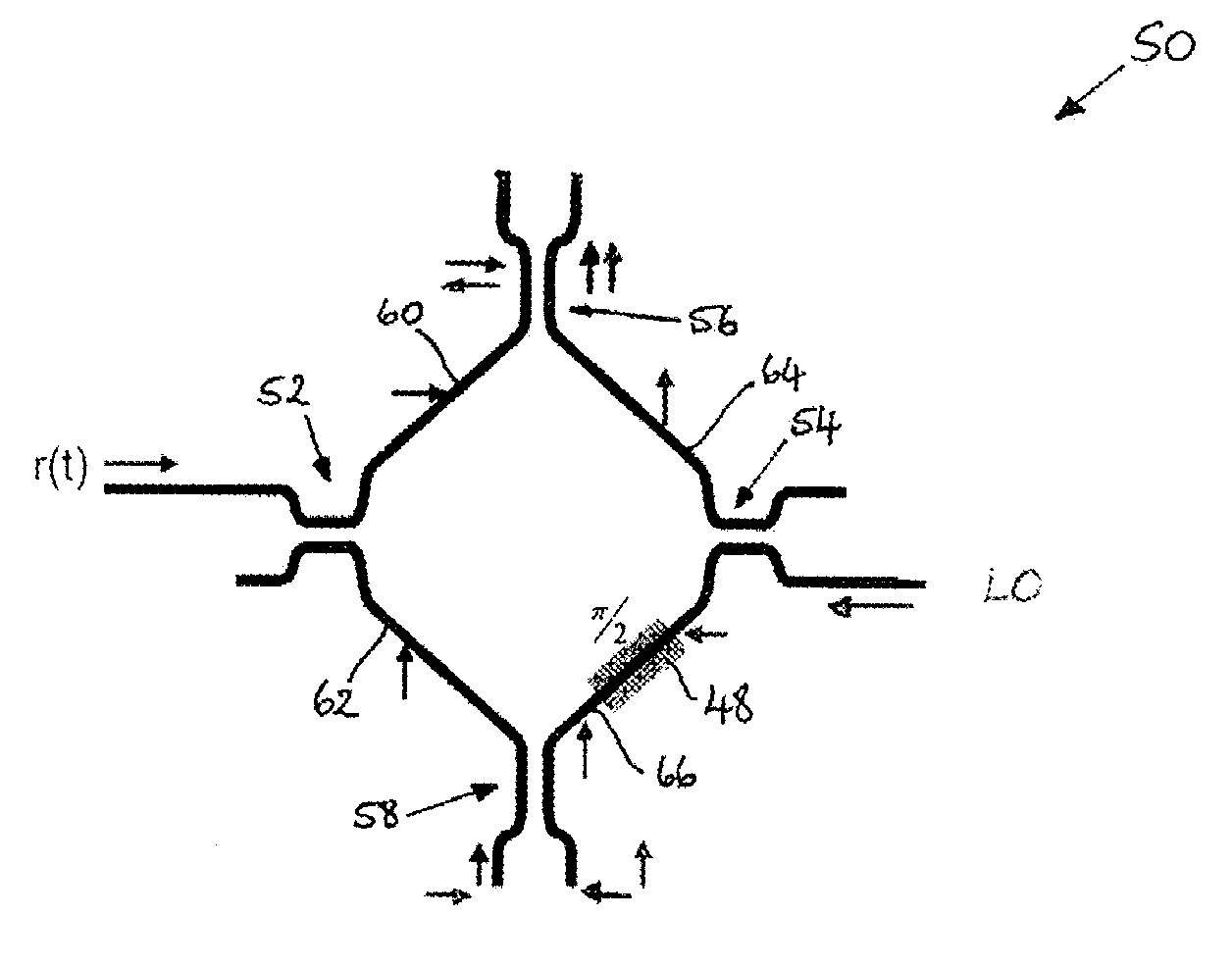
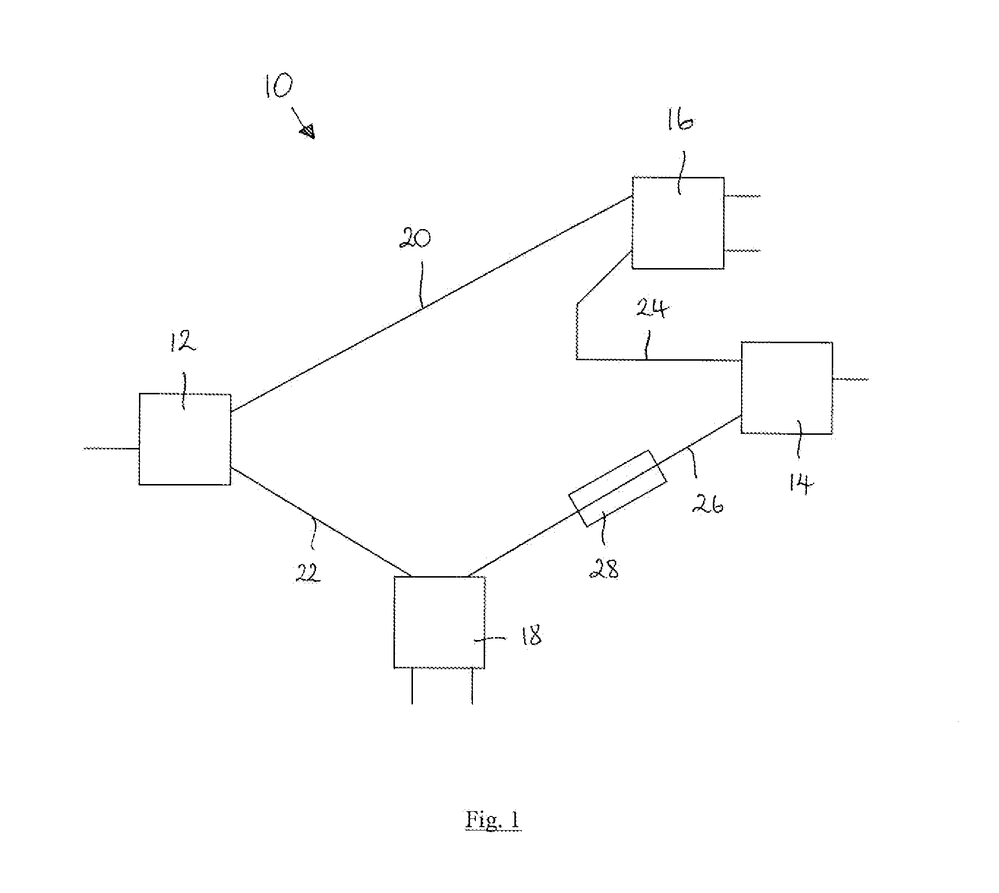
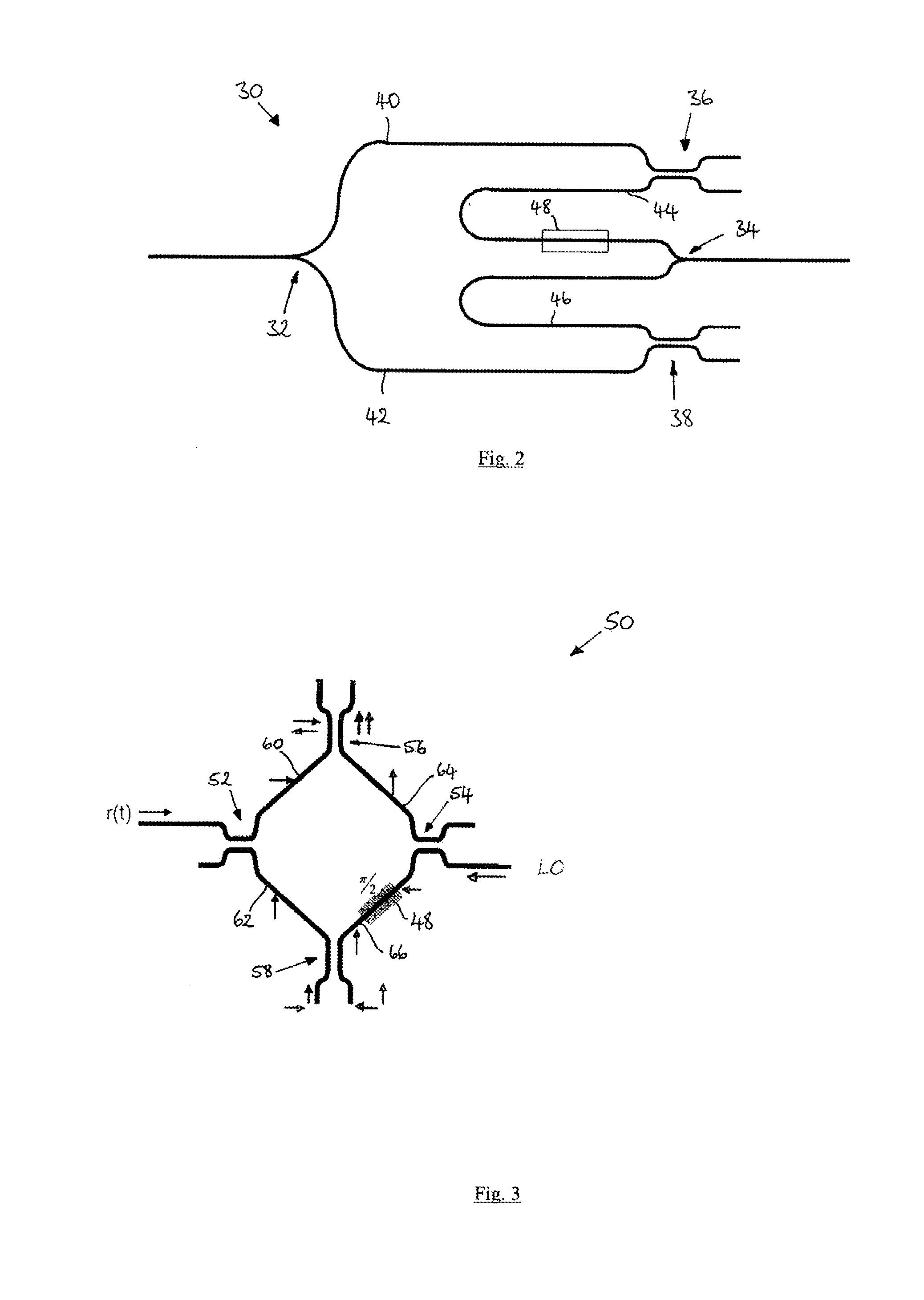
the invention provides a planar waveguide circuit 10 as shown in FIG. 1. The planar waveguide circuit 10 comprises a first optical splitter 12, a second optical splitter 14, a first optical signal combiner 16, a second optical signal combiner 18, four optical waveguides 20, 22, 24, 26 and a phase-shifter 28.

The first optical splitter 12 is arranged to receive an input optical signal. The second optical splitter 14 is arranged to receive a reference optical signal. Each optical splitter 12, 14 is arranged to split the optical power of a received optical signal into an in-phase component and a quadrature-phase component, respectively provided at the outputs of the optical splitters 12, 14. The construction and operation of optical splitters will be well known to the person skilled in the art.

The first and second optical waveguides 20, 22 are arranged to couple first and second outputs of the first optical splitter 12 to respective inputs of the first and second optical signal combiner...


PUM

PropertyMeasurementUnit
phaseaaaaaaaaaa
path lengthsaaaaaaaaaa
equivalent path lengthsaaaaaaaaaa

Abstract

A planar waveguide circuit comprises a first optical splitter to receive an input optical signal, a second optical splitter to receive a reference optical signal, a first optical signal combiner, and a second optical signal combiner. First and second optical waveguides are provided to couple first and second outputs of the first optical splitter to respective inputs of the first and second optical signal combiners. Third and fourth optical waveguides are provided to couple first and second outputs of the second optical splitter to respective inputs of the first and second optical signal combiners. A phase-shifter is provided located to affect the phase of an optical signal propagating in one of the third and fourth optical waveguides. The first and second optical splitters and the first and second optical signal combiners are arranged such that the first, second, third and fourth optical waveguides do not intersect one another.

Description

TECHNICAL FIELDThe invention relates to a planar waveguide circuit and to an optical receiver incorporating the planar waveguide circuit.BACKGROUND90 degree optical hybrids are widely used within coherent optical receivers to mix four in-phase and quadrature states (B; −B; jB; −jB) of a reference optical signal (B) with a signal to be detected (A). 90 degree optical hybrids are six-port optical devices which generally comprise a pair of linear dividers and a pair of optical signal combiners interconnected by four waveguides, one of which includes a 90 degree phase shifter. In a coherent optical receiver the four vectorial additions of the reference signal and the signal to be detected are detected at two pairs of balanced photodetectors. Various designs for a 90 degree optical hybrid are proposed in Seimetz et al, “Options, feasibility and availability of 2×4 90° hybrids for coherent optical systems”, Journal of Lightwave Technology, volume 24, number 3, pp. 1317-1322, March 2006. T...

Claims


Application Information

Patent Timeline
Patent Type & Authority Applications(United States)
IPC IPC(8): G02F1/035H04B10/60
CPCG02B6/12004G02B2006/12147G02B2006/1215G02B2006/12159G02F1/035G02B6/125G02B6/122G02B6/43H04B10/60
Inventor BONTEMPI, FRANCESCAPOTI, LUCABOGONI, ANTONELLA
Owner TELEFON AB LM ERICSSON (PUBL)
Why Eureka
Try Eureka