Machine for centrifugally shooting abrasives

a centrifugal shooting and abrasive technology, which is applied in the direction of machines/engines, mechanical equipment, manufacturing tools, etc., can solve the problems of troublesome blade replacement, large work for the side liners of the above configuration,

Active Publication Date: 2011-09-22
SINTOKOGIO LTD
View PDF11 Cites 10 Cited by
  • Summary
  • Abstract
  • Description
  • Claims
  • Application Information

AI Technical Summary

Problems solved by technology

However, the conventional machine for centrifugally shooting abrasives that has the above configuration still requires much work to replace the side liners.
Further, since the impeller is big and heavy, the work to replace the blades is troublesome.

Method used


Image

  • Machine for centrifugally shooting abrasives
  • Machine for centrifugally shooting abrasives
  • Machine for centrifugally shooting abrasives

Examples


Embodiment Construction

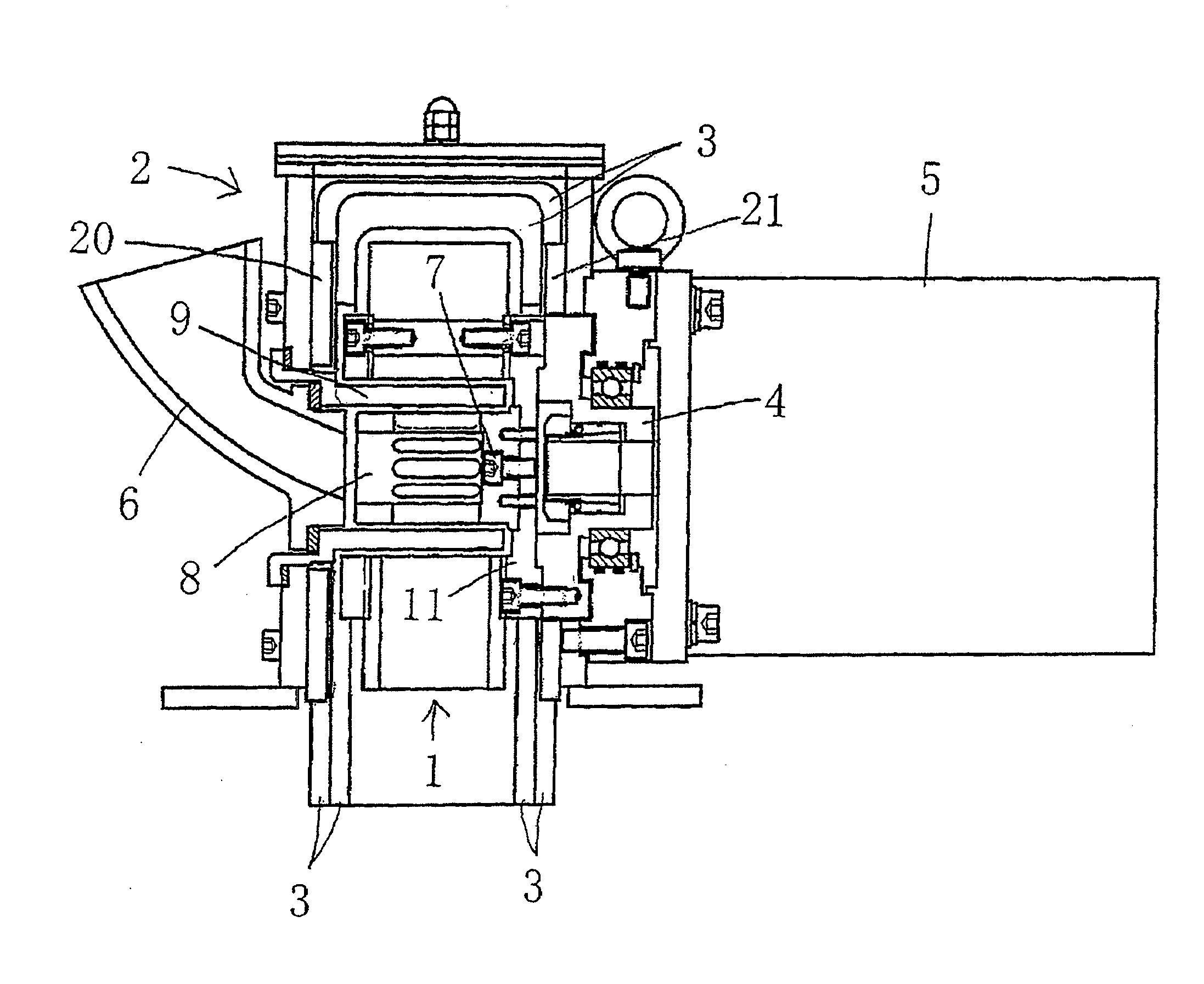
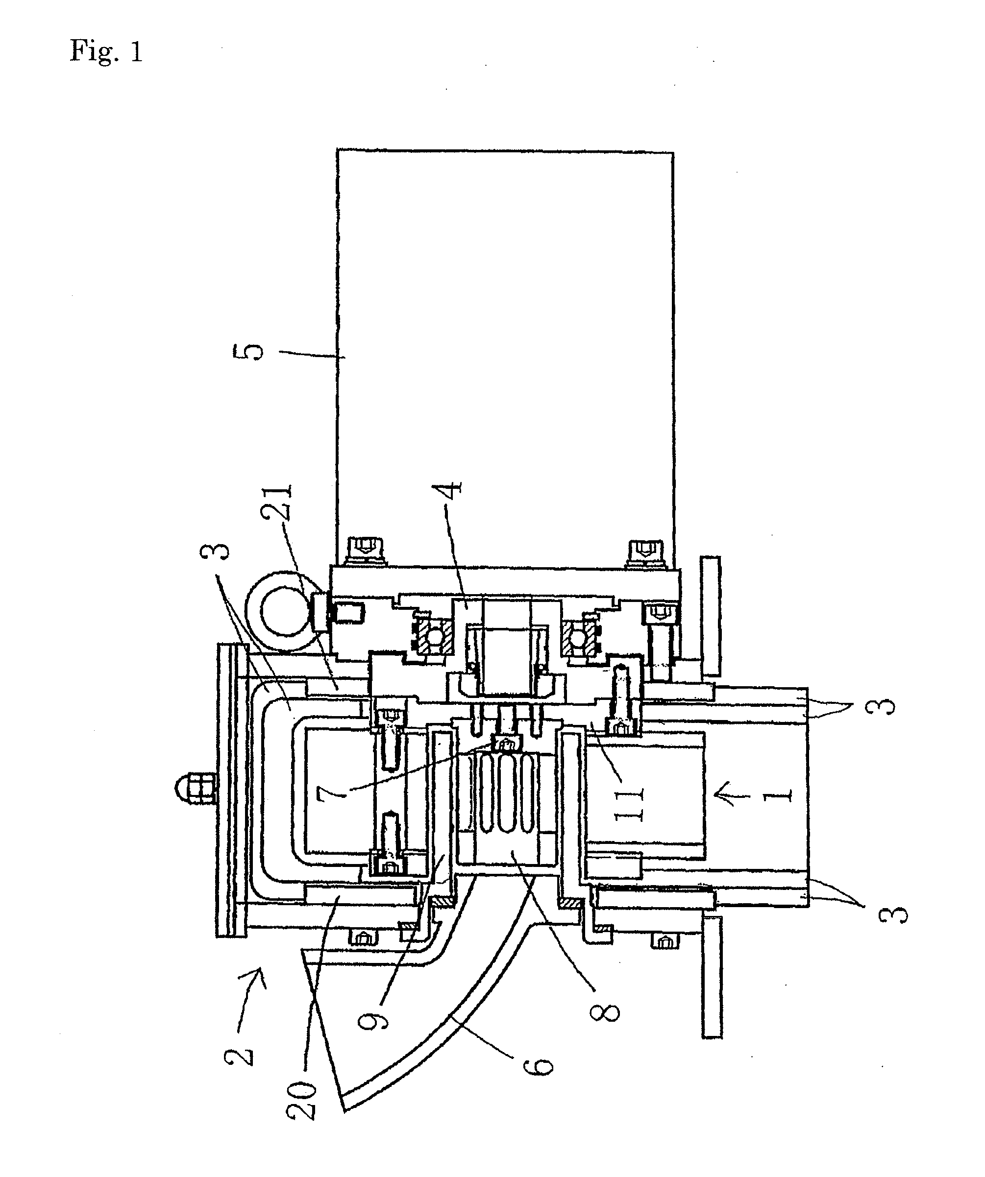
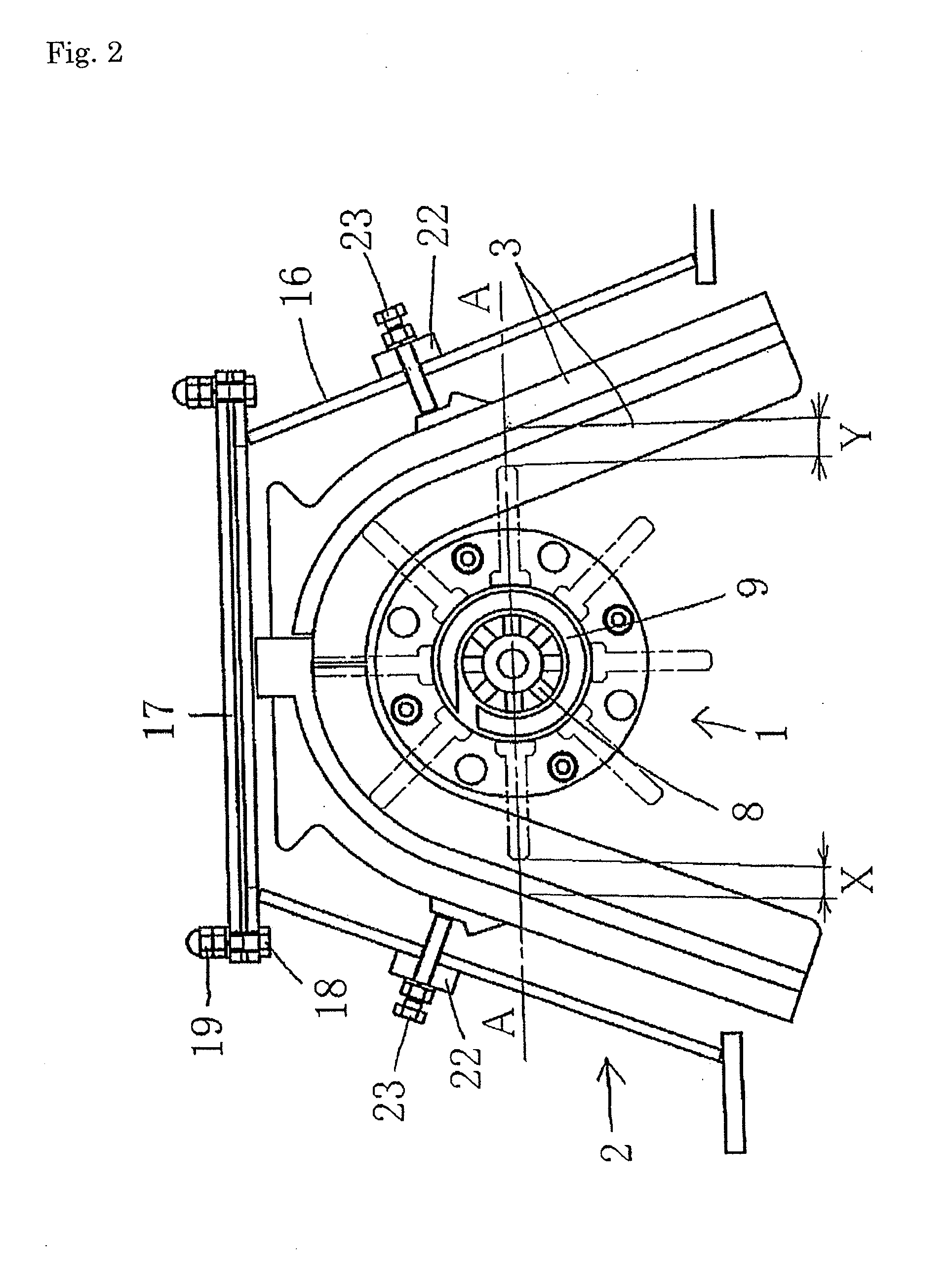
[0014]Below a machine for centrifugally shooting abrasives as an embodiment of the present invention is described with reference to FIGS. 1, 2, and 3. As shown in FIGS. 1 and 2, the machine for centrifugally shooting abrasives comprises an impeller 1 for centrifugally shooting the abrasives by the rotation of the impeller 1, a cover 2 for covering the impeller 1 to prevent the abrasives from being scattered, a side liner 3 for protecting, from the abrasives, the side wall of the cover 2 in the radial direction of the impeller 1, an electric motor 5 that is fixed, a guiding tube 6 attached to the cover 2 for guiding the abrasives to the inside of the impeller 1, a distributor 8 for distributing the abrasives that have been guided, and a control cage 9 for feeding the distributed abrasives to the impeller 1 in a controlled manner. The impeller 1 is mounted on a hub 4 that is fitted into the output shaft of the electric motor 5. The distributor 8 is detachably connected by a hexagonal ...


PUM


Abstract

A machine for centrifugally shooting abrasives that shoots the abrasives by rotation of an impeller is provided. In the machine, the impeller comprises a pair of disc-shaped side plates that face each other at a predetermined distance and a plurality of blades disposed between the side plates in the radial direction of the side plates. The impeller is mounted on a hub that is fitted into an output shaft of an electric motor. The impeller is covered by a cover. The side liner and blades of the machine can be easily replaced. A side liner 3 that is U-shaped with the longer side facing downward is detachably attached to the inner side of the cover 2. The upper part of the side liner is divisible into two parts. The side liner protects the side wall of the cover 2 from the abrasives that are shot from the impeller. The side liner has a U-shaped cross section. The impeller 1 is fixed to the hub 4 by screwing a bolt 15 on the hub 4 from the inner sides of the side plates 11. The diameter of the impeller 1 is limited to be 200 mm at maximum.

Description

TECHNICAL FIELD[0001]The present invention relates to a machine for centrifugally shooting abrasives. In particular, it relates to a machine for centrifugally shooting abrasives wherein an impeller comprises a pair of disc-shaped side plates that face each other with a predetermined distance between them and a plurality of blades disposed between the side plates in the radial direction of the side plates. The impeller is mounted on a hub that is fitted into an output shaft of an electric motor. The impeller is covered by a cover. Thus the abrasives are shot by the centrifugal force generated by the rotation of the impeller.BACKGROUND ART[0002]A typical example of conventional machines for shooting abrasives is disclosed in Japanese Patent No. 4085353. In that machine, the impeller comprises two side plates, i.e., a first side plate and a second side plate, and a plurality of blades. The impeller is mounted on the end of a rotating shaft. It is covered by a cover. The cover is protec...

Claims


Application Information

Patent Timeline
Patent Type & Authority Applications(United States)
IPC IPC(8): F01D5/14
CPCB24C5/066B24C5/062B24C5/06
Inventor ITO, MASAKATSUIWATA, KYOICHISHIGA, MASAJI
Owner SINTOKOGIO LTD
Why Eureka
Try Eureka