
Surgical instrument equipment appropriate for mini-invasive surgery

a surgical instrument and mini-invasive technology, applied in the field of surgical instrument equipment, can solve the problems of not being able to adjust to the different needs of variable angulation, and achieve the effect of clear maneuverability and control and greater operative scop

Active Publication Date: 2011-09-22
WOM IND SRL
View PDF11 Cites 27 Cited by
  • Summary
  • Abstract
  • Description
  • Claims
  • Application Information

AI Technical Summary

Benefits of technology

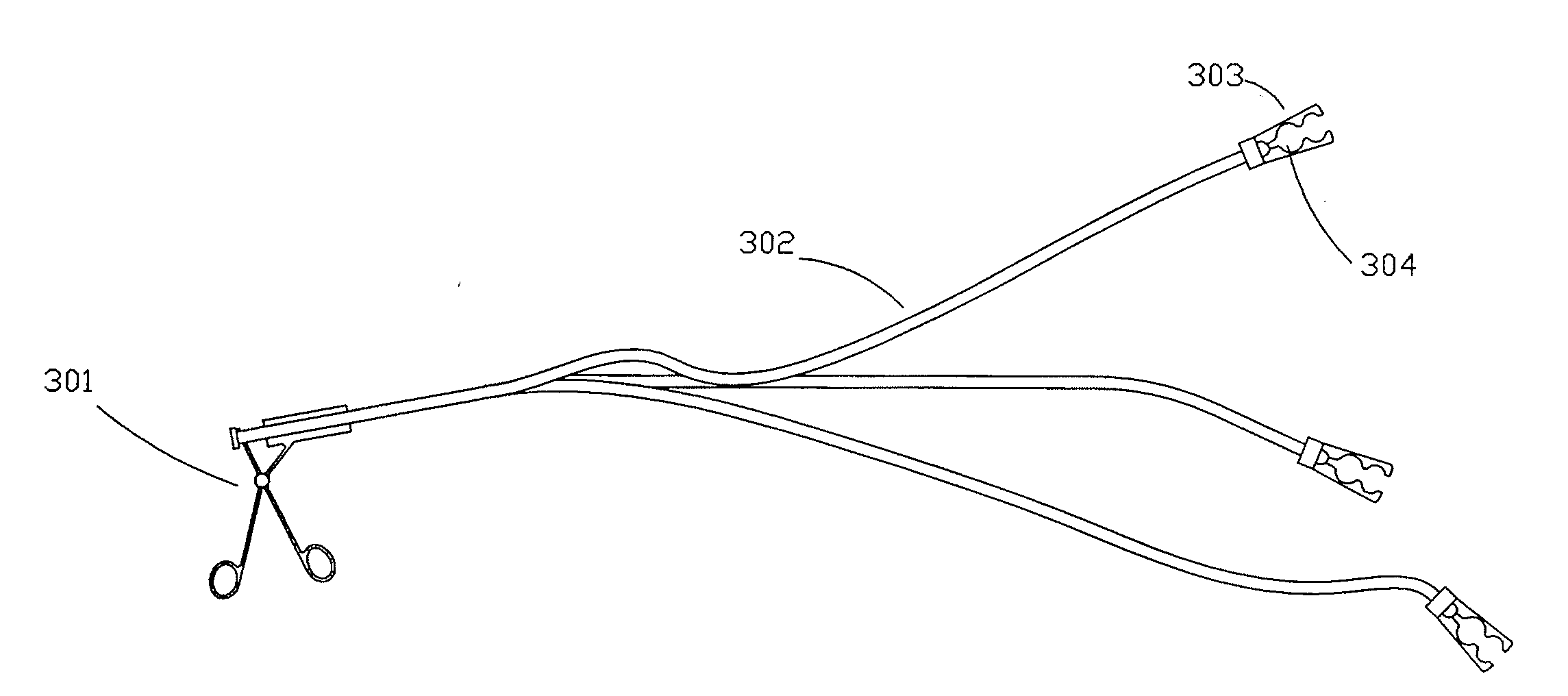
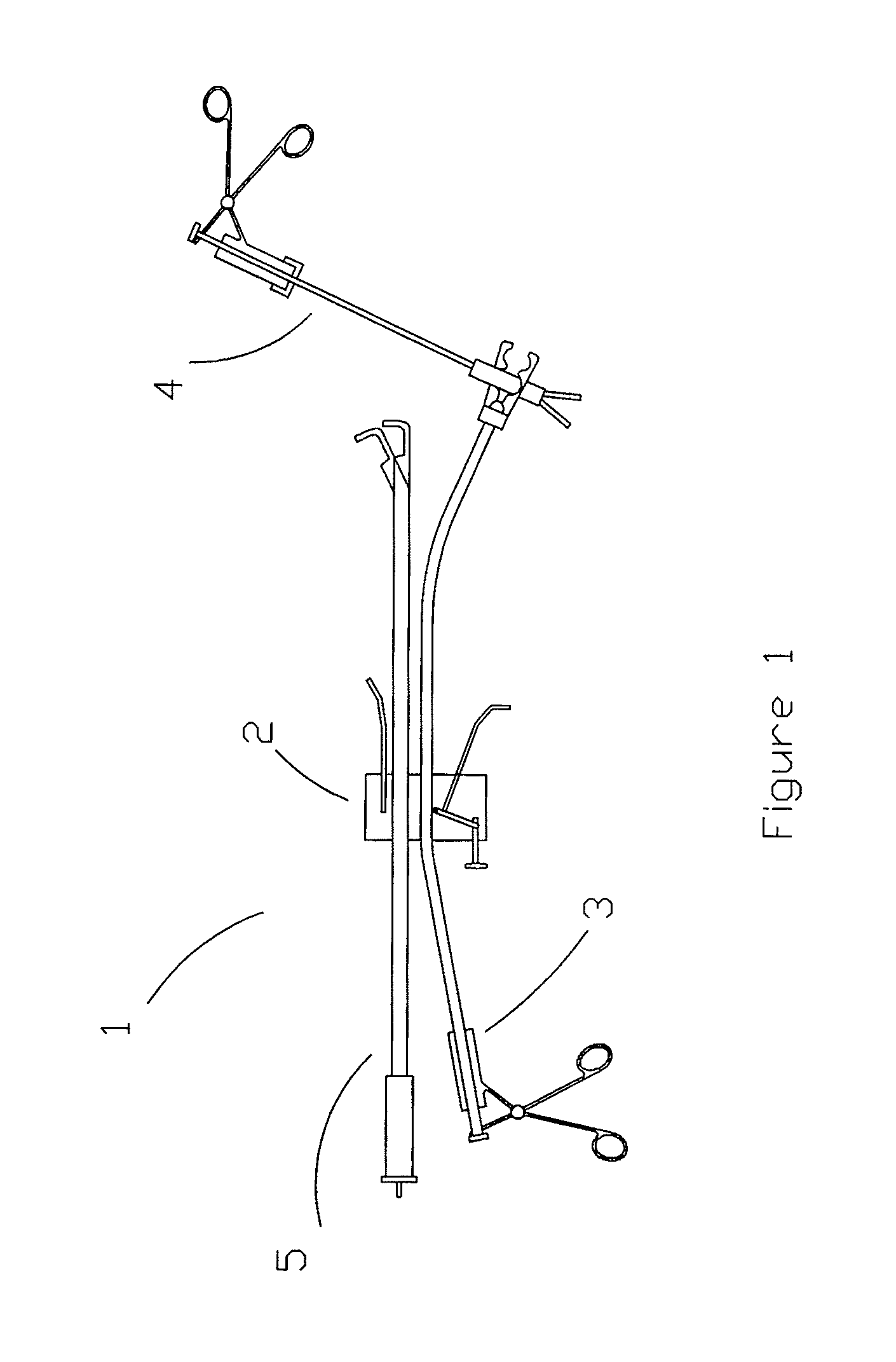
[0015]The object of the invention lies on the performance of surgical acts in which various operative devices inherent to surgery are manipulated through at least an access having an access device, said devices being mounted inside the patient's body, including an articulated element of cauterization and access of needle pliers through other accesses, allowing operation with several operative clamps that permit a clear maneuverability and control of the practice to be performed at different planes and angulations as the surgical technique may require, resulting in a minimum access surface and a greater operative scope.
[0018]Providing an equipment of surgical instruments suitable for minimally invasive surgery that allows the interchange of operative tips according to the different stages of the surgery without needing to perform other access incisions.
[0021]Providing an equipment of surgical instruments suitable for minimally invasive surgery which access port can allow the entrance of operative tools which operative head is of greater diameter than the average transmission diameter of said tools, which can allow to combine the concept of minimal access with a surgical practice being safer than that of the laparoscopy due to the size of the operative ends of the tools.
[0022]Providing a mounting clamp that transports heads of the needle pliers to the interior of the patient's cavity in different surgical acts and that allows the intrasurgical mounting of the needle plier permitting its coupling inside the patient's body.
[0023]Providing an articulated element of cauterization that may adopt different angulations at the surgical site, overcoming the limitations of rigid working elements.

Problems solved by technology

At present, since these laparoscopic instruments are rigid and function only on one directional axis, they are not adjustable to the different needs of variable angulation require either in space or at operative area.

Method used


Image

  • Surgical instrument equipment appropriate for mini-invasive surgery
  • Surgical instrument equipment appropriate for mini-invasive surgery
  • Surgical instrument equipment appropriate for mini-invasive surgery

Examples


first embodiment

[0047]In a first embodiment, the driving element of the clamp tips is of double articulation, as seen in FIGS. 4B and 4C. The double articulation is made up by a pair of clamp tips (428) joined by bolts to a pair of clamp articulations (426). The clamp articulations are flat elements, with thru holes on each of their ends. A first bolt (425) joins the orifices of proximal ends of the clamp articulations to the intrahead device by means of its distal thru hole. The clamp tips have a first thru hole at their proximal ends and a second thru hole in the middle of said tips and the first hole. Both clamp tips are joined by means of second bolts (429) at their proximal ends to the distal ends of the clamp articulations. By means of a third bolt (430) at its second holes, they are joined to the head (427). This set of elements make up an articulation which, when receiving the bi-directional movement of the driving intrahead device (422), causes the opening and closure of the clamp tips (42...

second embodiment

[0049]In a second embodiment, the driving element of the clamp tips is a single articulation, as seen in FIG. 4D. The head has a complete circumference (434) at its proximal end, the rest being only the basis (435). In the middle of the basis, a pair of flanges (436) opposite to a thru hole are provided. Between said pair of flanges, the proximal end of the single articulation (437) is lodged, which has a first thru hole, and this set is joined by a bolt (438). Near this first thru hole, a second thru hole is provided to which an end of the intrahead device is joined, by means of a bolt (439). In this embodiment, a joining element (440) is provided between said driving intrahead device (422) and the single articulation (437). This joining element is joined to the driving intrahead device and, at its distal end, a thru hole is provided, where the bolt is coupled (439), which bolt drives the single articulation (437). By means of the control, an axial movement of the intrahead device ...

third embodiment

[0050]In a third embodiment, the driving element of the clamp tips is an elastic type articulation, as seen in FIG. 4E. The head (427) has, at its proximal end, an internal thread (443) that finishes, at its distal end, in tubular shape. By the interior of the head, the driving intrahead device (422) moves freely, having, at the proximal side, an orifice (423) with internal thread (424) where the external thread (408) of the connecting needle (403) is coupled. Following the internal thread and in distal direction of the bolt, the latter is divided into two elastic, “V” shaped branches (441), forming the clamp tips. Each of these “V” shaped branches finishes in the form of a clamp to perform pression, disection, cutting, clipping, separating, suturing, cauterizating, etc. When the driving chuck is displaced in bi-directional movement (from proximal to distal or vice versa), given the elastic feature of the “V” shaped branches, the latter are driven apart or put together causing the o...


PUM


Abstract

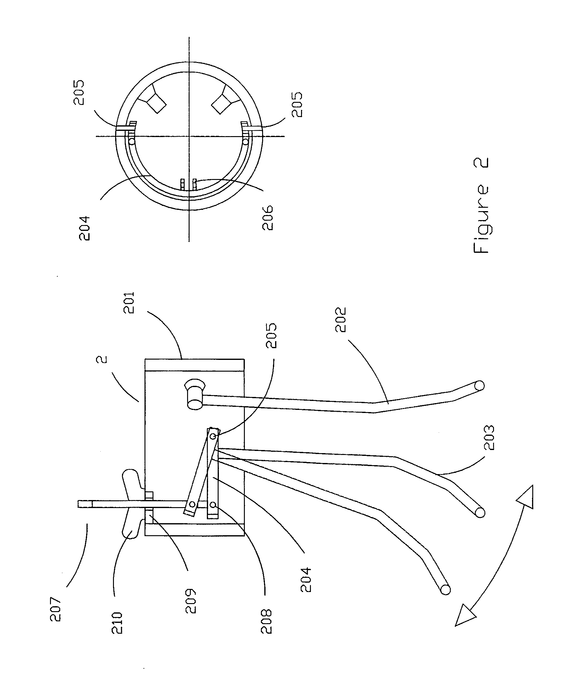
Equipment of surgical instruments suitable for minimally invasive surgery, comprised by a multivalve device with adjustable separator to enter the patient's body and with at least one access simultaneous port for a number of components which includes an operative surgical device comprised by a control, a movement transmission element and an operative mounting clamp of a needle plier comprised by a control, a head connecting sheath, with a connecting needle lodged in its interior and the operative head; and a cauterization device comprised by a control, a movement transmitting element and the cautery.

Description

1) TITLE AND TECHNICAL FIELD OF THE INVENTION[0001]The present invention relates to an equipment of surgical instruments suitable for minimally invasive surgery, defined by a number of operative pieces to be mounted inside the patient's cavity to be operated on.2) STATE OF THE ART AND PROBLEMS TO SOLVE[0002]At present, in the prior art, laparoscopic and endoscopic surgical instruments are known.[0003]In laparoscopic surgeries, multiple access ports or channels are used with several incisions on the skin, one for each access device. In turn, each access port allows the entrance of one laparoscopic instrument at a time through only one operative channel. At present, since these laparoscopic instruments are rigid and function only on one directional axis, they are not adjustable to the different needs of variable angulation require either in space or at operative area.[0004]In endoscopic surgery, instruments in use, contrary to laparoscopic instruments that have an extreme flexibility,...

Claims


Application Information

Patent Timeline
Patent Type & Authority Applications(United States)
IPC IPC(8): A61B17/00
CPCA61B17/0218A61B17/3423A61B18/1445A61B19/26A61B2017/2931A61B2017/2912A61B2017/3447A61B2019/267A61B2017/2904A61B90/57A61B90/50A61B17/34A61B17/29A61B18/04A61B18/12
Inventor ALTAMIRANO, JOSE DANIEL
Owner WOM IND SRL
Learn More