Portable gas monitor

a gas monitor and portable technology, applied in the field of portable gas monitors, can solve the problems of one or more components of the prior art portable monitors being prone to sluggishness and even failure, and the portable monitors are not designed to be parts,

Inactive Publication Date: 2011-09-22
ELKINS EARTHWORKS
View PDF2 Cites 70 Cited by
  • Summary
  • Abstract
  • Description
  • Claims
  • Application Information

AI Technical Summary

Benefits of technology

[0018]In still another and/or additional non-limiting aspect of the present invention, the portable monitor includes a plurality of pressure sensors. In one non-limiting embodiment of the invention, the portable monitor includes three or more three pressure sensors. The three or more pressure sensors enable the portable monitor to simultaneously measure three or more different pressures. For instance, when the portable monitor is used to measure pressures on a gas well wherein gas is being drawn by a vacuum (e.g., landfill well, etc.), the three or more pressure sensors enable an operator to simultaneously measure the static or applied vacuum pressure on the well, the impact or differential pressure on the well, and the available vacuum or header pressure that can be applied to the well. Prior art portable monitors for landfill wells only included two pressure sensors. These two pressure sensors were used to measure the applied vacuum pressure or static vacuum of the well. As such, if an operator wanted to measure the available vacuum pressure of the well, the operator had to disconnect one of the tubes from the applied vacuum port on the well and reconnect the tube at available pressure vacuum port on the well. This procedure was not only time consuming and inconvenient, especially in inclement weather, the accuracy of the data readings potentially could be compromised during the disconnecting and reconnecting of the vacuum tubes. These problems associated with prior portable monitors are overcome by the portable monitor of the present invention. The portable monitor of the present invention enables an operator to connect the portable monitor of the present invention to all three pressure ports on a well so that the applied or static vacuum pressure, the differential pressure, and the available vacuum pressure of the well can be determined without having to further reconnect and disconnect vacuum tubes.
[0019]In yet another and/or additional non-limiting aspect of the present invention, the portable monitor is a multi-unit system. In one non-limiting embodiment of the invention, the portable monitor includes a separate control unit and a separate measuring unit. Prior art portable monitors were in the form of a single unit. This single unit design required the operator to temporarily mount the portable monitor on a portion of the well or at a region about the well, connect all of the sensors and/or pressure tubes to the well, and then press multiple buttons on the portable unit to perform the required tests for the well. This single unit design of the prior art portable monitor made it inconvenient and difficult for the operator to take readings and perform the required operations on the monitor while the portable monitor was mounted on or about the well. During inclement weather, the taking of readings from the prior art portable monitor and the performing of the required operations on the portable monitor made such testing even ...

Problems solved by technology

The portable monitor is also not designed to be part of an automated control system for the well.
However, the portable monitor of the present invention is not generally designed to provide constant control of the well.
In prior art portable monitors, one or more components of a prior art portable monitor was prone to sluggishness and even failure when the portable monitor was used in a cold environment (i.e., temperature of less than about 30-40° F.).
As such, it was difficult, ...

Method used


Image

  • Portable gas monitor
  • Portable gas monitor
  • Portable gas monitor

Examples


Embodiment Construction

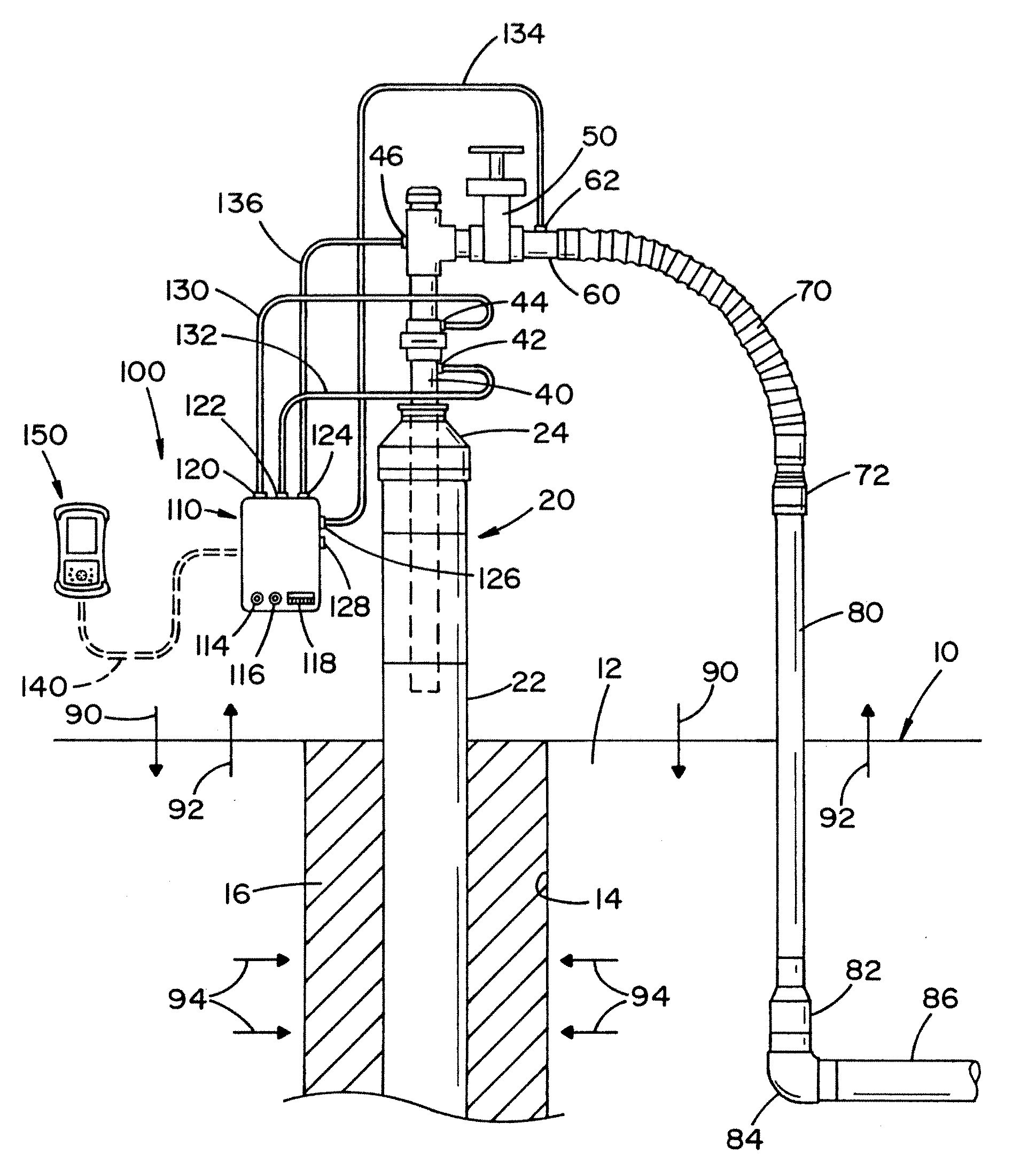
[0043]The solid waste and environmental industry uses field technicians to measure, monitor and store environmental information at particular industrial sites and landfill sites. When measuring gases from a landfill well, information regarding methane, carbon dioxide and oxygen is desirable to determine the environmental impact of the landfill and the potential energy from methane gas that can be obtained from the landfill. The present invention is directed to a portable monitor that can be used by field technicians to obtain gas flow rates and gas composition from landfill wells and will be described with particular reference thereto; however, it will be appreciated that the portable monitor of the present invention can be used in other or additional applications.

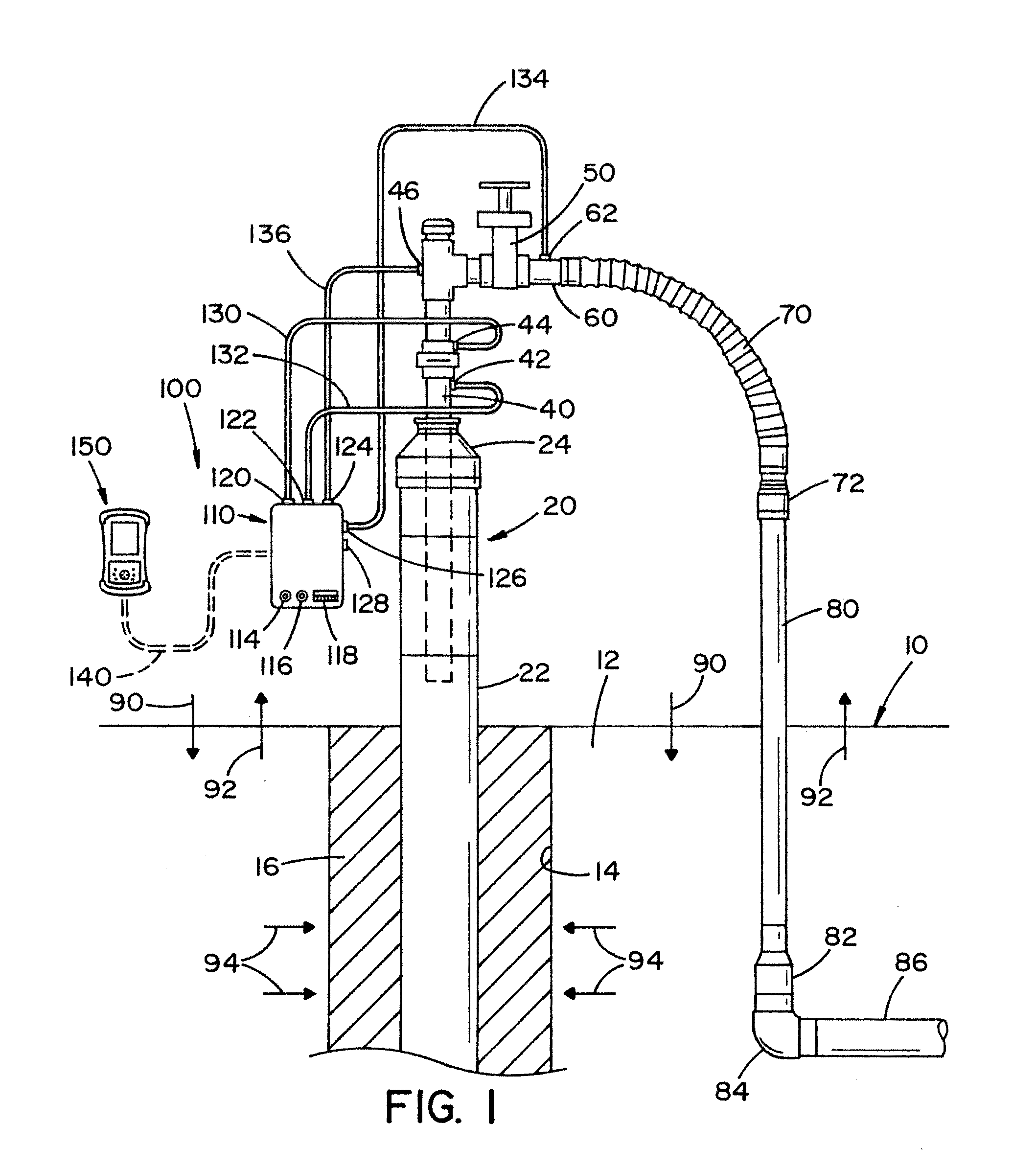
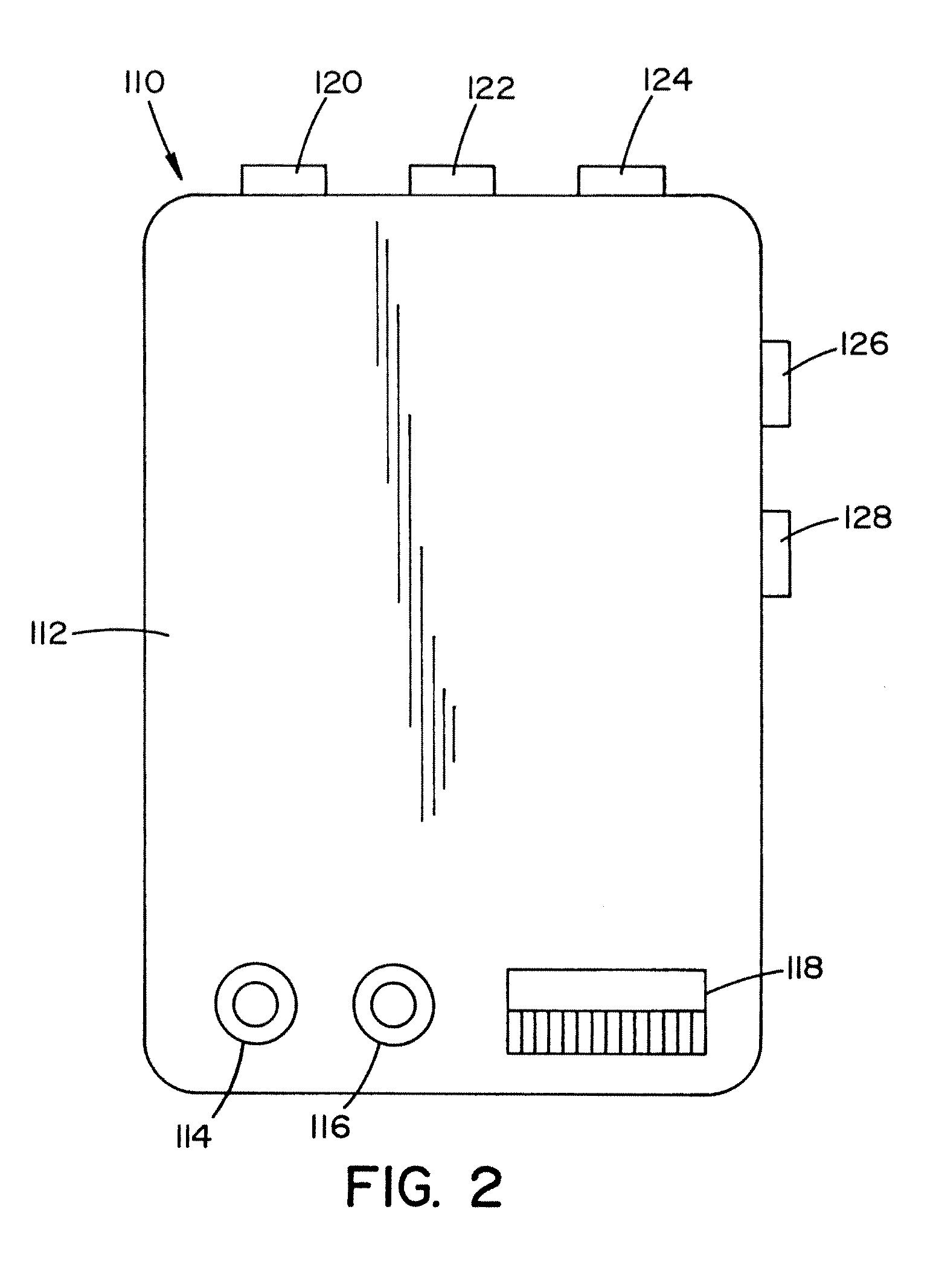
[0044]Referring now to the drawings wherein the showing is for the purpose of illustrating a non-limiting preferred embodiment of the invention only and not for the purpose of limiting the same, FIG. 1 illustrates a conven...


PUM


Abstract

A portable monitor used to measure landfill gas and landfill well parameters. The portable monitor includes a control unit and a measuring unit that can communicate wirelessly with one another. The control unit and/or measuring unit can include a heating arrangement to increase the temperature of one or more components in the control unit and/or measuring unit in cold environments.

Description

[0001]The present patent application is a continuation-in-part of U.S. patent application Ser. No. 11 / 634,186 filed Dec. 5, 2006, which is incorporated herein by reference. The present application also claims priority on U.S. Provisional Application Ser. No. 61 / 452,655 filed Mar. 17, 2011, which is incorporated herein by reference.[0002]The present invention is directed to portable fluid monitoring systems, particularly to a portable fluid monitoring system used to measure fluid pressure and / or fluid composition, and even more particularly to a portable gas monitoring system used to measure gas pressures and compositions of gasses at a plurality of different wells that are located in a location remote from one another. The portable fluid monitor is particularly useful in measuring gas pressures and compositions of gasses from landfill wells; however, the portable fluid monitor can be used for other or additional applications.BACKGROUND OF THE INVENTION[0003]Landfills are commonly fo...

Claims


Application Information

Patent Timeline
IPC IPC(8): G06F19/00G01K7/02
CPCE21B47/00B09B1/00G01V9/007E21B47/07E21B49/0875E21B47/06E21B49/08E21F7/00G01V11/002
Inventor ELKINS, CHARLES
Owner ELKINS EARTHWORKS
Why Eureka
Try Eureka