Caliper brake device

a brake device and caliper technology, applied in the direction of fluid-actuated brakes, mechanical devices, transportation and packaging, etc., can solve the problems of brake pad deformation, brake pad deflection, friction surface deformation, etc., and achieve the effect of increasing efficiency and stable braking for

Inactive Publication Date: 2011-09-29
RAILWAY TECH RES INST +1
View PDF4 Cites 17 Cited by
  • Summary
  • Abstract
  • Description
  • Claims
  • Application Information

AI Technical Summary

Benefits of technology

[0008]It is therefore an object of this invention to increase the efficiency with which a fluid press

Problems solved by technology

As a result, a reaction force against the pressing force may cause the brake pad to deflect and the friction surface to deform.
Further, a local temperature increase may occur on the brake pad, leading to a reduction in a frictional coefficient of the brake pad, and as a result, the brake pad may be unable to exhibit an expected braking forc

Method used


Image

  • Caliper brake device
  • Caliper brake device
  • Caliper brake device

Examples


Embodiment Construction

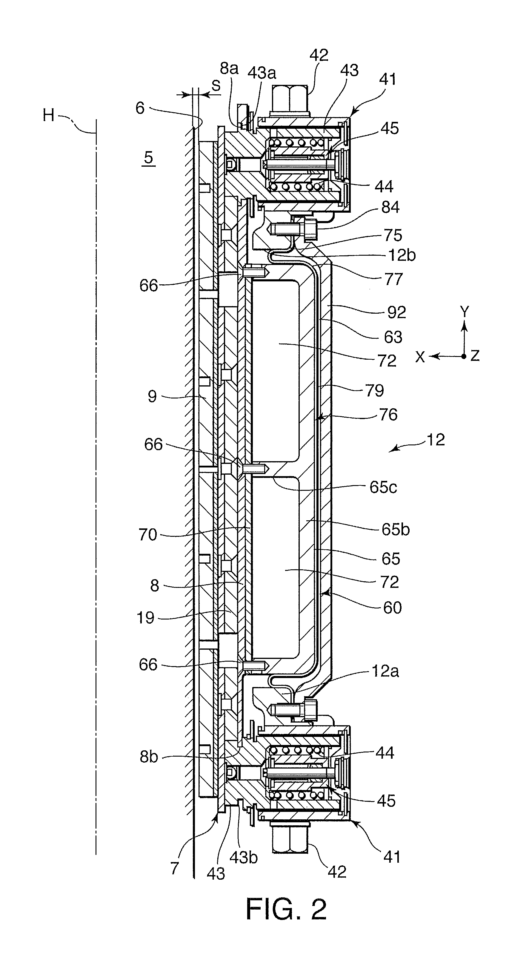
[0016]Referring to FIG. 2 of the figures, in a caliper brake device for a railway vehicle, braking surfaces 6 formed on respective side faces of a vehicle wheel 5 are sandwiched between a pair of brake pads 7 in order to apply a brake to rotation of the vehicle wheel 5. An X axis, a Y axis, and a Z axis in the figure correspond to an axle direction of the vehicle wheel 5, a vertical direction, and a front-rear direction, respectively. A dot-dash line H in the figure denotes a central axis of the vehicle wheel 5.

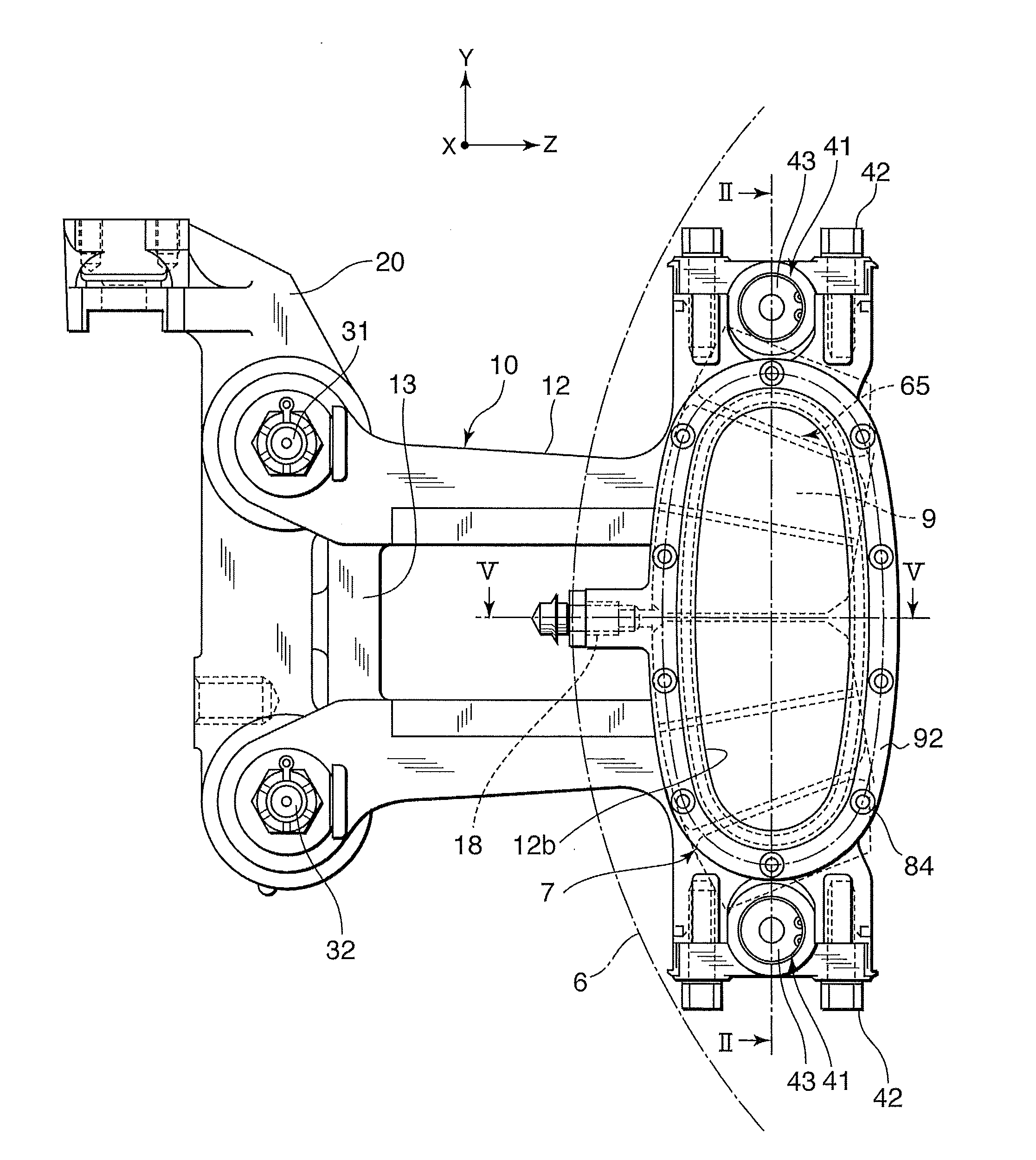
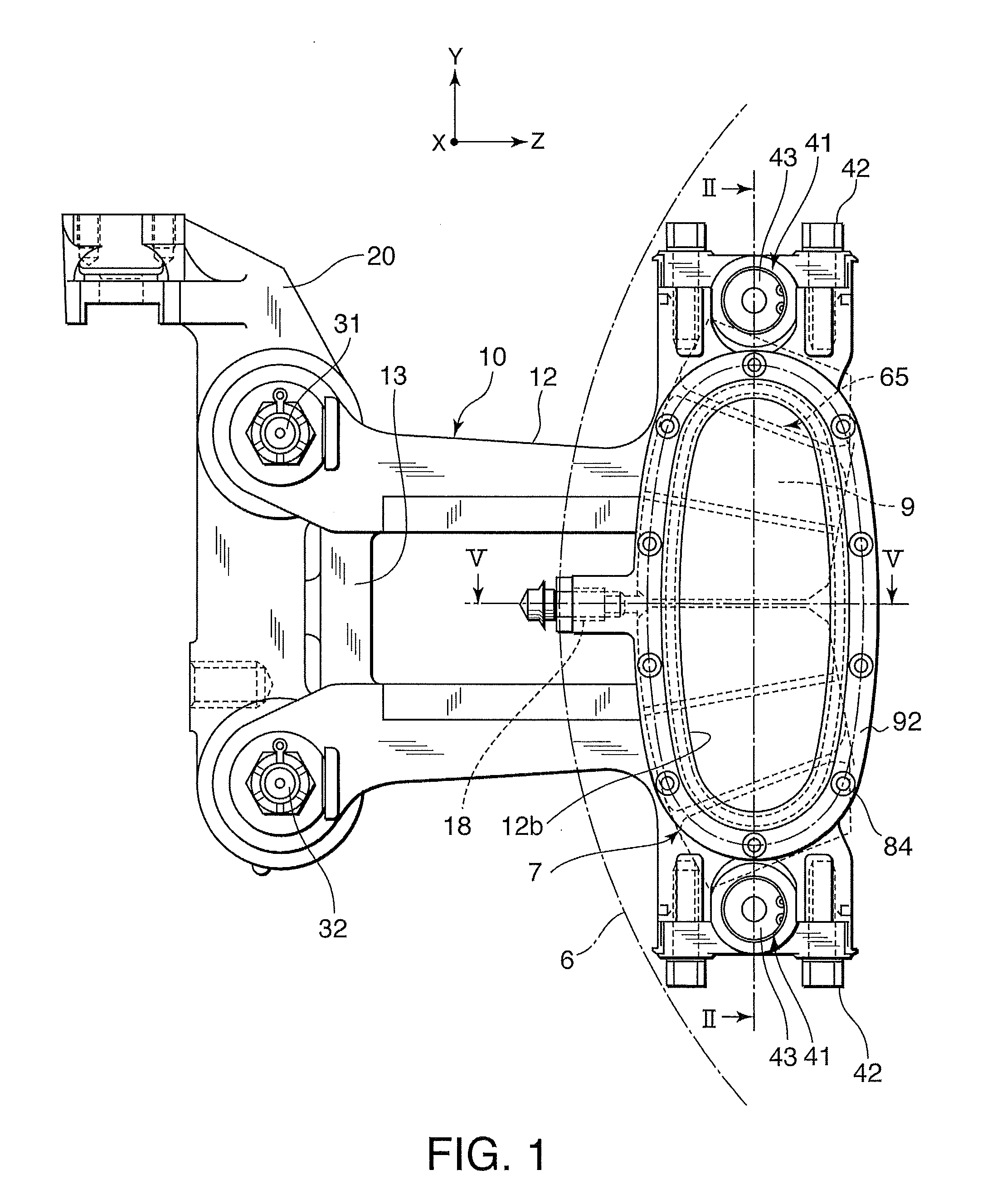
[0017]Referring to FIG. 1, a caliper main body 10 of the caliper brake device is supported by a support frame 20 fixed to a vehicle body of the railway vehicle to be capable of sliding in the X axis direction of the figure via slide pins 31 and 32. Here, the vehicle body includes a bogie.

[0018]A floating support structure for the caliper main body 10 is a well-known structure disclosed in WO2009 / 048161 and WO2009 / 060993, the contents of which are incorporated herein by refere...


PUM


Abstract

In a vehicle caliper brake device, a brake pad 7 supported by a holder 8 applies a frictional force to a braking surface 6 as a diaphragm actuator 60 is driven. The holder 8 is supported by a caliper main body 10 to be capable of displacing in a displacement direction of the brake pad 7. The diaphragm actuator 60 includes a piston 65 that is driven by a diaphragm 76 to push the holder 8. The piston 65 is fixed to the holder 8 using a plurality of screws 66, and therefore the piston 65 applies a pressing force to the brake pad 7 uniformly without the need for guidance by a guide.

Description

FIELD OF THE INVENTION[0001]This invention relates to a caliper brake device which applies a frictional force to a braking surface that rotates integrally with a vehicle wheel.BACKGROUND OF THE INVENTION[0002]A railway vehicle is typically installed with a pneumatic-hydraulic converter that converts an air pressure supplied from an air pressure source into an oil pressure, whereby a hydraulic brake is activated using the oil pressure supplied from the pneumatic-hydraulic converter via an oil pressure pipe.[0003]With regard to this point, JPH08-226469A and JPH08-226471A, published by the Japan Patent Office in 1996, disclose a hydraulic brake device for a railway vehicle in which a hydraulic cylinder presses a brake pad against a friction surface of a rotary body such as a brake rotor in accordance with a supplied oil pressure.[0004]By installing a pneumatic brake that is activated by an air pressure supplied from an air pressure source in the railway vehicle, on the other hand, it i...

Claims


Application Information

Patent Timeline
IPC IPC(8): B61H5/00F16D55/228F16D65/20B61H13/00F16D65/18
CPCF16D65/18F16D65/54F16D2125/12F16D2121/02F16D2055/0091F16D65/0075F16D55/2245F16D2125/06F16D2121/08
Inventor SUZUKI, TSUTOMUOOKAWARA, YOSHIYUKIKARINO, YASUSHI
Owner RAILWAY TECH RES INST
Why Eureka
Try Eureka