Electrical heating element

a heating element and heating wire technology, applied in the field of electric heating elements, can solve the problems of high labor costs and insufficient operation of the conventional arrangement of the heating wire coil in the multi-hole tube, and achieve the effect of reducing labor costs and ensuring the production of heating elements

Inactive Publication Date: 2011-09-29
LEISTER TECHNOLOGIES
View PDF4 Cites 20 Cited by
  • Summary
  • Abstract
  • Description
  • Claims
  • Application Information

AI Technical Summary

Benefits of technology

[0006]The invention addresses the problem of proposing an electrical heating element that is of technologically simpler construction and can therefore be produced more cost-efficiently, and that also operates without problems over the long term, independent of the air conditions.

Problems solved by technology

Conventional arrangements of the coils in the multi-hole tube are not sufficient for operation under all prevailing air flows and pressure conditions.
In addition, the labor required for manufacturing the heating element with a heating wire coil guided through the air channels of the multi-hole tube is costly.

Method used


Image

  • Electrical heating element
  • Electrical heating element
  • Electrical heating element

Examples


Embodiment Construction

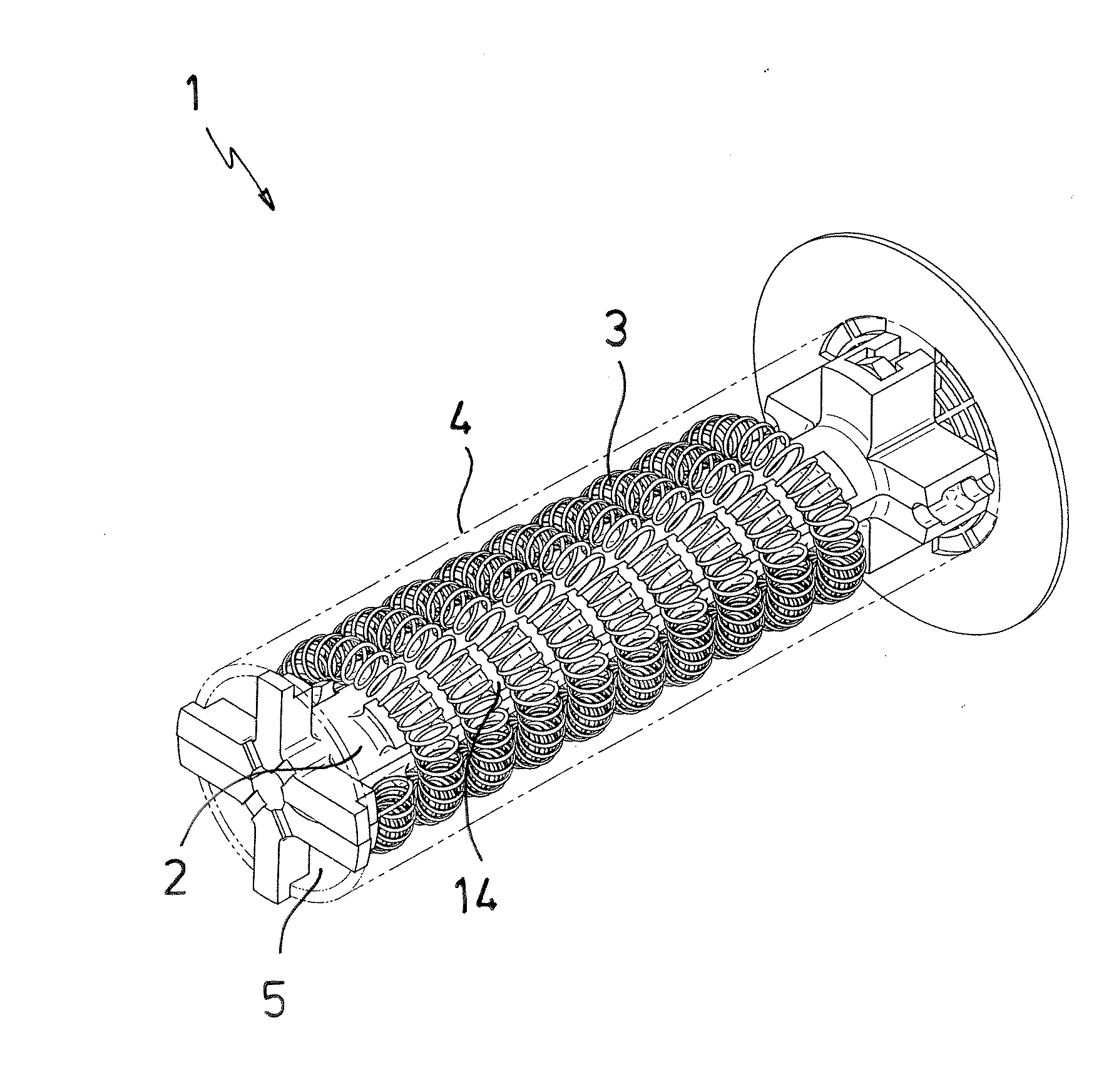
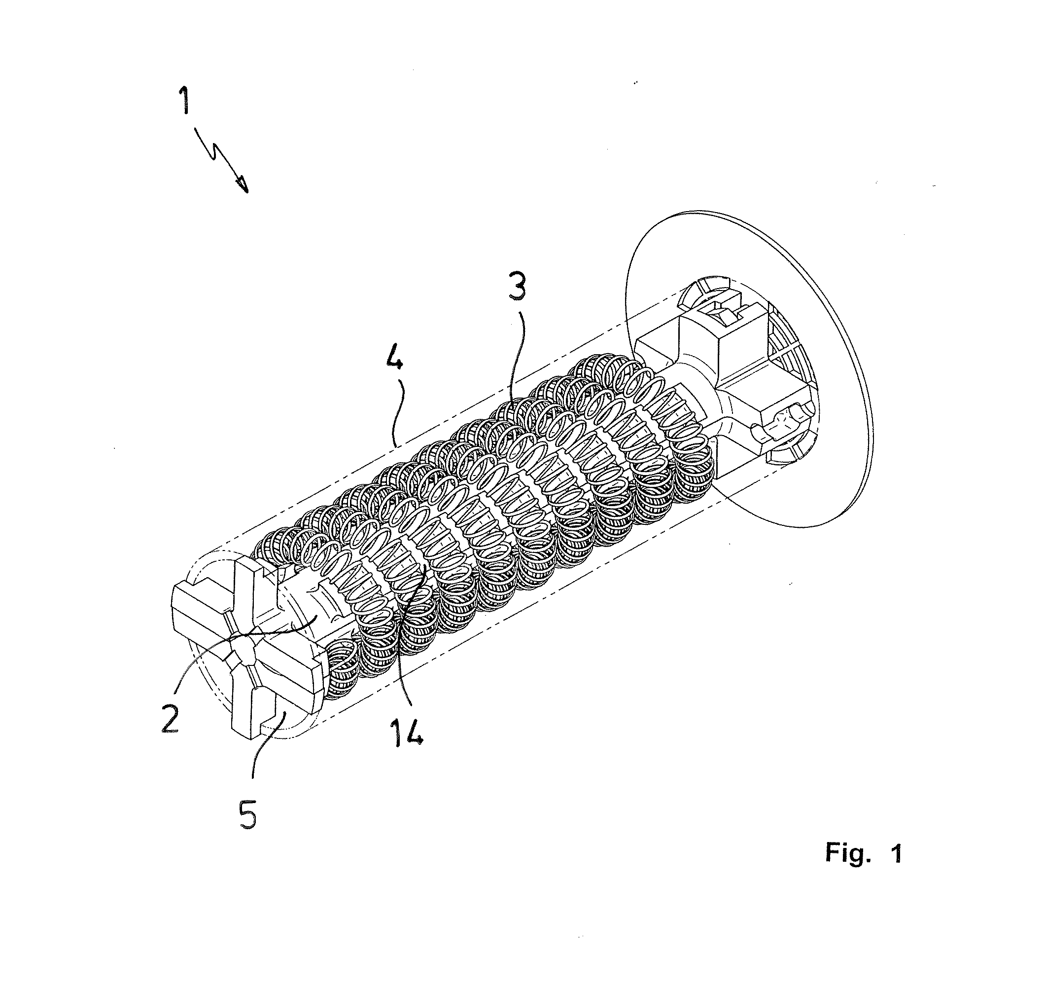
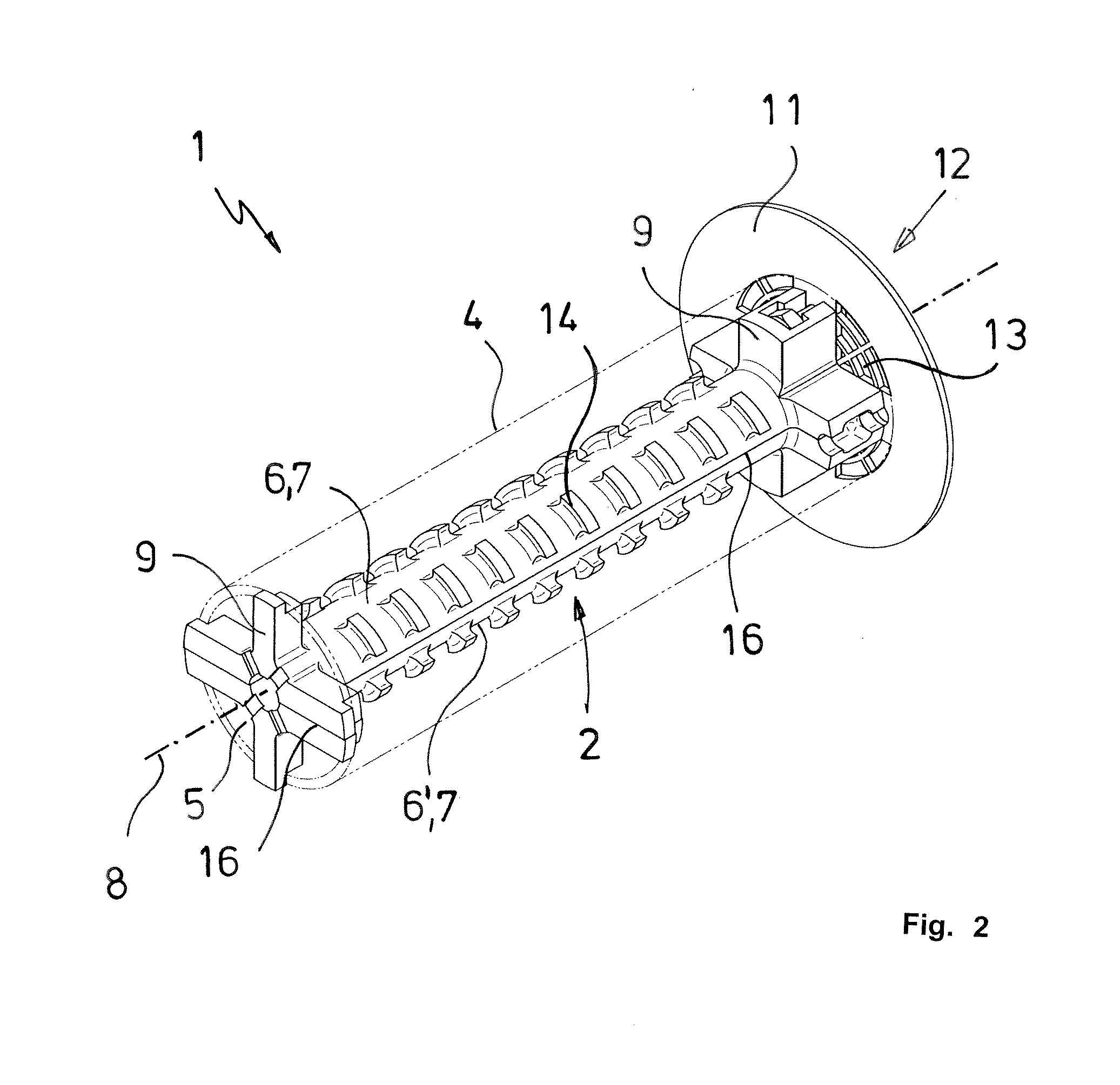
[0030]FIG. 1 shows a heating element 1 according to the invention that comprises an elongated coil carrier 2 for accepting a heating wire coil 3. The heating wire coil 3 is held by the coil carrier 2 that is made of a thermally resistant, electrically insulating material such as ceramic in a spiral-like arrangement. In FIG. 2, the heating wire coil 3 of the heating element 1 is not shown to allow an unimpeded view of the coil carrier 2. The heating wire coil 3 is enclosed by a sleeve tube 4 that is also made of a thermally resistant material. The coil carrier 2 and the sleeve tube 4 delimit an air channel 5 of the electrical heating element through which the heating wire coil 3 passes in the longitudinal direction and that extends over the entire axial length of the heating element 1. The coil carrier 2 is composed of two coil carrier shell parts 6, 6′. For the purpose of illustration, FIG. 5 shows the coil carrier 2 by itself in a perspective view with the coil carrier shell parts ...


PUM


Abstract

Electrical heating element 1, preferably for the ignition of biomass heating systems such as pellet stoves, with an elongated coil carrier 2 that is made of a thermally resistant, electrically insulating material and is designed to accept a heating wire coil, where the heating wire coil is held spiral-like on the outside the coil carrier 2 and is enclosed by a sleeve tube 4 also made of a thermally resistant material. The coil carrier 2 and the sleeve tube 4 delimit an air channel 5 through which the heating wire coil passes. According to the invention, the coil carrier 2 comprises at least two adjacent coil carrier shell parts 6, 6′ that extend symmetrically to the center axis 8 of the heating element 1 in the longitudinal direction of the coil carrier 2.

Description

CROSS-REFERENCE TO RELATED APPLICATION[0001]The present application claims priority under 35 USC §119 to German Patent Application No. 20 2010 004 133.3 filed Mar. 25, 2010, the entire disclosure of which is incorporated herein by reference.TECHNICAL FIELD OF THE INVENTION[0002]The invention concerns an electrical heating element, preferably for the ignition of a pellet heating system or some other biomass heating system or of related stoves, with an elongated coil carrier made of a thermally resistant, electrically insulating material designed to accept a heating wire coil, where the heating wire coil is held spiral-like on the outside the coil carrier and is enclosed by a sleeve tube made of a thermally resistant material, and where the coil carrier and the sleeve tube delimit an air channel through which the heating wire coil passes.DESCRIPTION OF THE RELATED ART[0003]Wood pellet heating systems or other biomass heating systems are an alternative technology for oil and gas heatin...

Claims


Application Information

Patent Timeline
Patent Type & Authority Applications(United States)
IPC IPC(8): H05B3/06
CPCH05B2203/022H05B3/46
Inventor GUBLER, ULRICHOTT, SIMON
Owner LEISTER TECHNOLOGIES
Why Eureka
Try Eureka