Rotor and permanent magnet rotating machine

a rotating machine and permanent magnet technology, applied in the direction of rotating parts of magnetic circuits, magnetic circuits characterised by magnetic materials, magnetic circuit shapes/forms/construction, etc., can solve the problem that the diffusion method has not been considered effective in the ipm rotation machine, and achieve high magnetic coercive force, and high residual magnetic flux density

Active Publication Date: 2011-09-29
SHIN ETSU CHEM IND CO LTD
View PDF10 Cites 8 Cited by
  • Summary
  • Abstract
  • Description
  • Claims
  • Application Information

AI Technical Summary

Benefits of technology

[0012]However, the present inventors have found that increase of the magnetic coercive force only in the surface region which has been subjected to the diffusion is useful in the larger generator of the IPM rotating machine. The diffusion treatment is considered to have an effect of increasing the magnetic coercive force in the region of from surface to depth of less than 5 mm. Increase in the magnetic coercive force is considered to gradually become smaller at a deeper position from the surface of the magnet. We have found that increase of the magnetic coercive force is extremely effective in the region of from the surface to depth of about 3 mm in the IPM rotating machine of the large wind power generator.
[0013]In the large wind power generator, measures against natural disasters are important and it is necessary to consider magnet demagnetization in all situations especially in the permanent magnet rotating machine. The most severe magnet demagnetization condition is a large diamagnetic field due to a short-circuit current of the generator. Such a short-circuit current is caused by breakage of a device for controlling output of the generator due to a lightning strike, for example. This short-circuit current is several times as high as the current during rated operation and a diamagnetic field at this time is also several times larger. The short-circuit current generated in the coils causes a large flow of a magnetic flux through a stator, a clearance and a rotor. Part of the flow of the magnetic flux acts as the diamagnetic fields on the magnets and causes the demagnetization. Major part of the magnetic flux flows into the rotor core which is made of soft magnetic material and part of it leaks into the magnets. It has been found that the leaked magnetic flux flows especially into a region of from a stator-side surface to a depth of 3 mm or less of the magnet in a rotating machine used in a large generator having a rated output of 1 MW or higher, the rotating machine comprising a rotor having a diameter of 500 mm or greater. In other words, it has been found that it is possible to reduce a possibility of demagnetization to a large extent by increasing the magnetic coercive force in the region of about 3 mm in the stator side.
[0015]As described above, the present inventors have considered that the above approach of increasing the coercive force by diffusing Dy or Tb in a coating method or a sputtering method is very effective as a measure against the magnet demagnetization of the IPM rotating machine of the large wind power generator. By using the magnets in which the magnetic coercive force is increased in the stator-side region by such a approach, it is possible to prevent the demagnetization when the short-circuit current flows through the generator to generate the large diamagnetic fields in the stator-side region of the magnets and it is possible to increase the output of the rotating machine because of the higher residual magnetic flux density than the other approaches which increase the magnetic coercive force.
[0018]According to the invention, by using a rotor comprising one or more permanent magnets having a high residual magnetic flux density and a high magnetic coercive force, especially a high magnetic coercive force in the surface region close to the stator, it is possible to provide the IPM rotating machine having high output and high demagnetization resistance and being suitable for the magnet generator of the large wind power generation.

Problems solved by technology

Accordingly, the diffusion method has not been considered effective in the IPM rotation machine.

Method used


Image

  • Rotor and permanent magnet rotating machine
  • Rotor and permanent magnet rotating machine
  • Rotor and permanent magnet rotating machine

Examples


example 1

[0045]A plurality of rectangular Nd-based sintered magnets having dimensions of 100 mm by 100 mm by 20 mm and magnetized in a direction of the thickness 20 mm were provided and subjected to the diffusion treatment. The diffusion treatment was carried out by mixing granular dysprosium fluoride with ethanol, immersing the magnets in this mixture wherein faces of each of the magnets excluding one face perpendicular to the magnetization direction were masked, and then heating the magnets in an Ar atmosphere at 900° C. for an hour. Cubes with a side length of 1 mm were cut out from a portion between the center of the face having subjected to the diffusion treatment and the depth at a distance of 1 mm from the treated face, and from an inner central portion, respectively, of one of the magnets. Then magnetic coercive forces measured were 1700 kA / m for the diffusion-treated face of the magnet and 1200 kA / m for the inner central portion of the magnet.

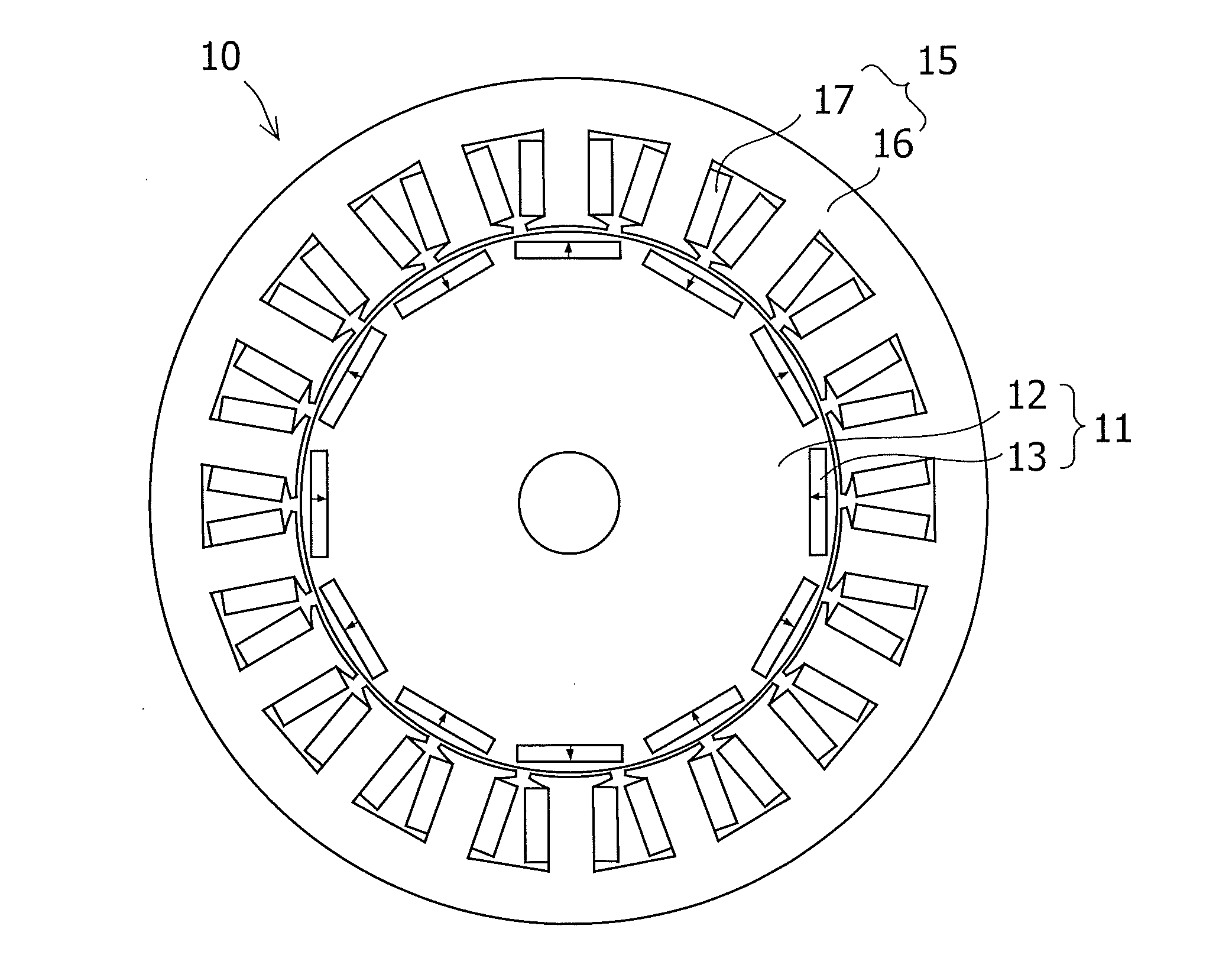
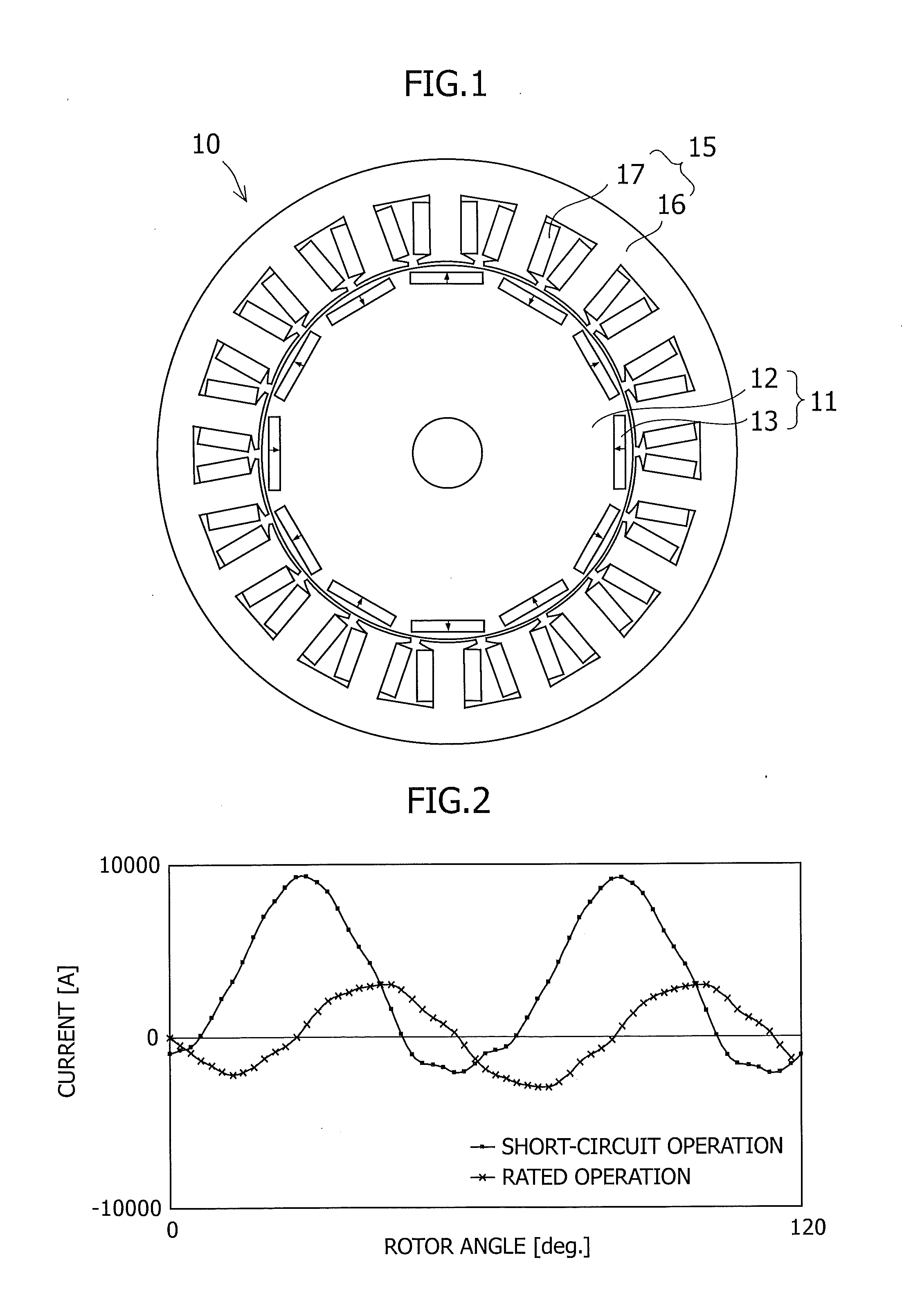
[0046]The magnets were mounted in a 12-p...

example 2

[0048]A plurality of magnets made of the same material and having the same dimensions as those in Example 1 were provided, immersed in the same diffusion treatment solution as that in Example 1 without being masked, and heated in the same manner as in Example 1. Cubes with a side length of 1 mm were cut out from a portion between the centers of the six faces having subjected to the diffusion treatment and the depths at a distance of 1 mm from the centers of the treated six faces, and from an inner central portion, respectively, of one of the magnets. Then magnetic coercive forces measured were 1700 kA / m for each of the six diffusion-treated faces of the magnet and 1200 kA / m for the inner central portion of the magnet.

[0049]The magnets were mounted in the same generator as in Example 1, the same short-circuit test was conducted, and electromotive force was measured before and after the test. As a result, the electromotive force was the same before and after the short-circuit test, ex...


PUM


Abstract

A rotor adapted for a large permanent magnet rotating machine having high output and demagnetization resistance and the permanent magnet rotating machine are provided. More specifically, there is provided a rotor adapted for a permanent magnet rotating machine, the machine comprising the rotor and a stator disposed with a clearance from an outer peripheral face of the rotor and formed by winding a winding wire through a stator core having two or more slots, the rotor comprising one or more permanent magnets in each of two or more insertion holes, the insertion holes being formed in a circumferential direction in a rotor core, wherein a magnetic coercive force in a stator-side surface region of each of the permanent magnets is greater than that in an inner central portion by 300 kA / m or more, the inner central portion being an inner portion at a depth of at least 5 mm from every outer shape face of the permanent magnet. There is also provided the permanent magnet rotating machine comprising this rotor and a stator disposed with a clearance from an outer peripheral face of the rotor and formed by winding a winding wire through a stator core having two or more slots.

Description

CROSS-RELATED APPLICATIONS[0001]This application claims priority from Japanese Patent Application No. 2010-066145; filed Mar. 23, 2010, the disclosure of which is incorporated herein by reference in its entirety.BACKGROUND OF THE INVENTION[0002]The present invention relates to a rotor used for a permanent magnet rotating machine comprising the rotor comprising a plurality of permanent magnets embedded in a rotor core and a stator formed by winding a winding wire through a stator core having a plurality of slots, the rotor and the stator disposed with a clearance interposed therebetween (which the machine is so-called a magnet-embedded rotating machine or an IPM (interior permanent magnet) rotating machine), and particularly to a rotor adapted for a permanent magnet rotating machine best suited for a large wind power generator and the like.[0003]An Nd-based sintered magnet is used for more and more various purposes because of its excellent magnetic properties. In recent years, in a f...

Claims


Application Information

Patent Timeline
Patent Type & Authority Applications(United States)
IPC IPC(8): H02K1/27
CPCH02K1/02H02K21/16H02K1/276H02K1/2766H02K15/03H02K21/44H02K1/274
Inventor KOBAYASHI, HIDEKIDOI, YUHITOMINOWA, TAKEHISA
Owner SHIN ETSU CHEM IND CO LTD
Why Eureka
Try Eureka