

Apparatus for generating electricity
a technology for generating electricity and apparatus, applied in the direction of generator/motor, transducer diaphragm, instruments, etc., can solve the problems of energy conversion efficiency, and achieve the effects of generating electricity easily scaled up and down, excellent durability and manufacturing, and easy operation
- Summary
- Abstract
- Description
- Claims
- Application Information
AI Technical Summary
Benefits of technology
Problems solved by technology
Method used
Image


Examples
first embodiment
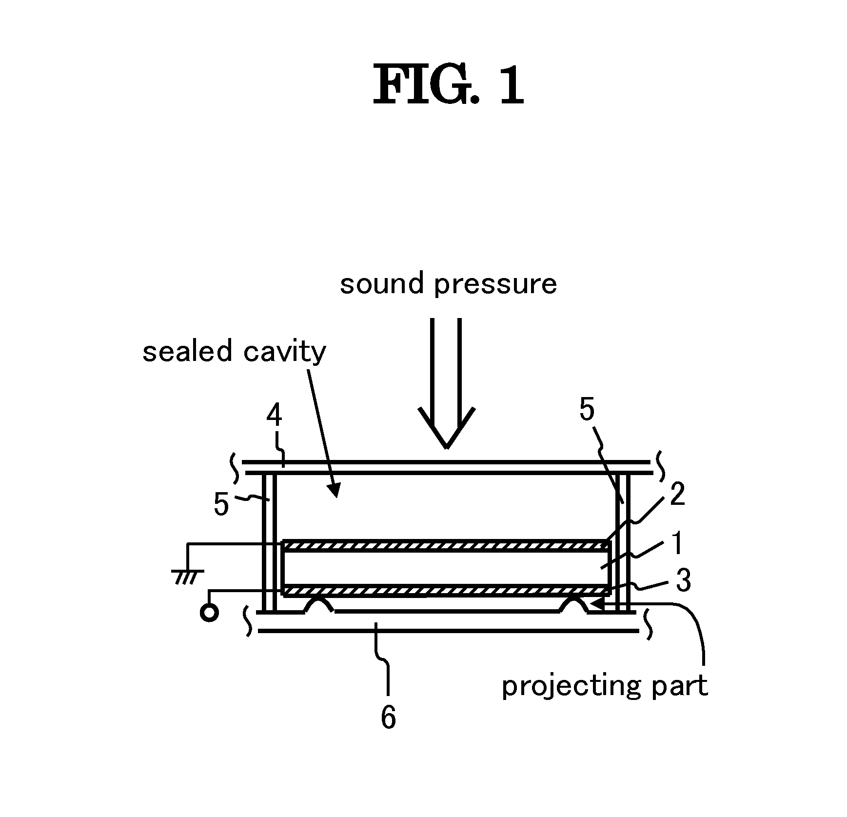
[0041]FIG. 1 shows a fragmentary sectional view of an apparatus for generating electricity according to the present invention. The apparatus for generating electricity comprises piezoelectric substrate 1, electrode 2, electrode 3, vibration plate 4, side-wall unit 5 and supporting board 6. Piezoelectric substrate 1, having a rectangular pillar-shape, is made of a piezoelectric ceramic with dimensions of 0.24 mm in thickness (T), 40.1 mm in length (L), and 7.5 mm in width (W), and has two end surfaces vertical to the thickness direction thereof, the polarization axis thereof being parallel to the thickness direction thereof. In this time, it is possible to use a piezoelectric polymer film as piezoelectric substrate 1. Electrodes 2 and 3, made of aluminum thin films, are formed on two end surfaces of piezoelectric substrate 1, respectively. Vibration plate 4 has almost the same acoustic impedance as piezoelectric substrate 1. Supporting board 6 has two projecting parts. Thus, vibratio...
second embodiment
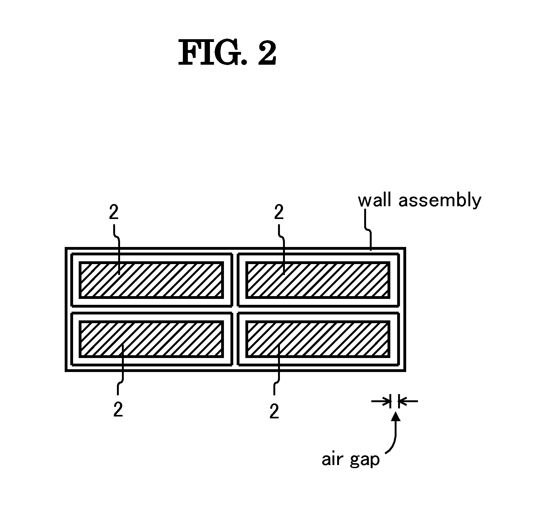
[0047]FIG. 6 shows a top plan view of the apparatus for generating electricity according to the present invention. The apparatus for generating electricity has the same construction as FIG. 1 except for using not one but six piezoelectric substrates 1 involved in side-wall unit 7 that is in place of side-wall unit 5. Thus, FIG. 6 shows only side-wall unit 7 and six piezoelectric substrates 1 covered with electrodes. Vibration plate 4, side-wall unit 7, supporting board 6 and six piezoelectric substrates 1 form one cavity resonator as FIG. 6. It is desired that all the piezoelectric substrates 1 are laid out separately, and are not cemented to side-wall unit 7, but situated to make a narrow air gap between each piezoelectric substrate 1 and side-wall unit 7. The cavity resonator in FIG. 6 can be used not only singularly but also collectively.
[0048]The apparatus for generating electricity in FIG. 6 is substantially equivalent in function to the apparatus in FIG. 1. The introduction of...
third embodiment
[0049]FIG. 7 shows a top plan view of the apparatus for generating electricity according to the present invention. The apparatus for generating electricity has the same construction as FIG. 1 except for using piezoelectric substrate 8 in place of piezoelectric substrate 1, and supporting board 6 without projecting parts. FIG. 7 shows only piezoelectric substrate 8 covered with electrodes. Piezoelectric substrate 8 has a square plate-shape with dimensions of 0.23 mm in thickness (T) and 18.8 mm in both length (L) and width (W), and the polarization axis thereof is parallel to the thickness direction thereof. Piezoelectric substrate 8 has electrodes 9 and 10 in place of electrodes 2 and 3, respectively, and is bonded to supporting board 6 at several surface-spots thereof via fixing means, for example, several adhesive masses. Electrodes 9 and 10 can be electrically divided into four square parts, respectively. In this way, electrode 9 comprises electrode-parts 91, 92, 93 and 94, and e...
PUM
 Abstract
Description
Claims
Application Information