Discharge control apparatus

a control apparatus and discharge control technology, applied in electric power, electric vehicles, transportation and packaging, etc., can solve the problems of increasing the battery load, affecting the reliability of the inverter, and the inability to quickly discharge the residual charge of the smoothing capacitor, etc., to achieve simple pause in control, improve reliability, and determine quickly and favorably

Inactive Publication Date: 2011-09-29
AISIN AW CO LTD
View PDF0 Cites 36 Cited by
  • Summary
  • Abstract
  • Description
  • Claims
  • Application Information

AI Technical Summary

Benefits of technology

[0008]According to the first aspect, the backup power supply is provided, and therefore the standby power does not increase. Further, the residual charge in the smoothing capacitor can be discharged quickly when the main switch is OFF. Furthermore, the discharge control unit that generates the discharge control signal for operating the switching element constituting the inverter in the active region and applies the generated discharge control signal to the switching element is provided independently of the driver circuit for applying the switching control signal when the inverter operates normally, and therefore the residual charge in the smoothing capacitor of the inverter can be discharged via the switching element of the inverter quickly, for example, even when a defect occurs in the control apparatus, and thus control of the inverter becomes difficult and the main switch turns OFF.
[0009]Here, the discharge control apparatus according to a second aspect of the present invention may further include an interference prevention unit that prevents interference between the switching control signal and the discharge control signal. The switching control signal and the discharge control signal are both input into a control terminal (a gate or a base) of the switching element. Further, the driver circuit that applies the switching control signal to the switching element is constituted independently of the discharge control unit that applies the discharge control signal to the switching element. Therefore, by providing the interference prevention unit that prevents interference between the switching control signal and the discharge control signal and in particular permits application of the switching control signal by the driver circuit during a normal operation, an improvement in reliability is achieved.
[0010]The discharge control apparatus according to a third aspect of the present invention may further include a voltage reduction detection unit that detects a voltage reduction in a driver power supply that supplies an operating power to the driver circuit, wherein when a voltage of the driver power supply falls below a predetermined discharge start voltage, the discharge control unit generates the discharge control signal and applies the generated discharge control signal to the switching element. The discharge control unit preferably discharges the residual charge quickly when the inverter stops operating normally, or in other words when the switching element is no longer controlled via the driver circuit. If an operation of the discharge control unit is determined simply according to the presence of the switching control signal, the discharge control unit may be operated during a simple pause in the control. The driver circuit operates upon reception of the driver power supply. Therefore, when the voltage of the driver power supply decreases, it may be determined that the inverter is no longer operating normally and the switching element is no longer being controlled via the driver circuit due to disconnection of the main switch or the like, rather than a simple pause in the control. In other words, by monitoring the voltage of the driver power supply, it can be determined quickly and favorably that the inverter is no longer operating normally and that discharge of the smoothing capacity is required. According to this constitution, the discharge control apparatus includes the voltage reduction detection unit, and therefore the discharge control unit can start the discharge control quickly on the basis of the detection result obtained by the voltage reduction detection unit.

Problems solved by technology

This firm power constitutes so-called standby power, and therefore the overall standby power of the vehicle increases, leading to an increase in a battery load.
Therefore, when a defect occurs in the control device, leading to a problem in control of the inverter such that the main switch is turned OFF, it may be impossible to discharge the residual charge of the smoothing capacitor swiftly.
Furthermore, the discharge control unit that generates the discharge control signal for operating the switching element constituting the inverter in the active region and applies the generated discharge control signal to the switching element is provided independently of the driver circuit for applying the switching control signal when the inverter operates normally, and therefore the residual charge in the smoothing capacitor of the inverter can be discharged via the switching element of the inverter quickly, for example, even when a defect occurs in the control apparatus, and thus control of the inverter becomes difficult and the main switch turns OFF.

Method used


Image

  • Discharge control apparatus
  • Discharge control apparatus
  • Discharge control apparatus

Examples


Embodiment Construction

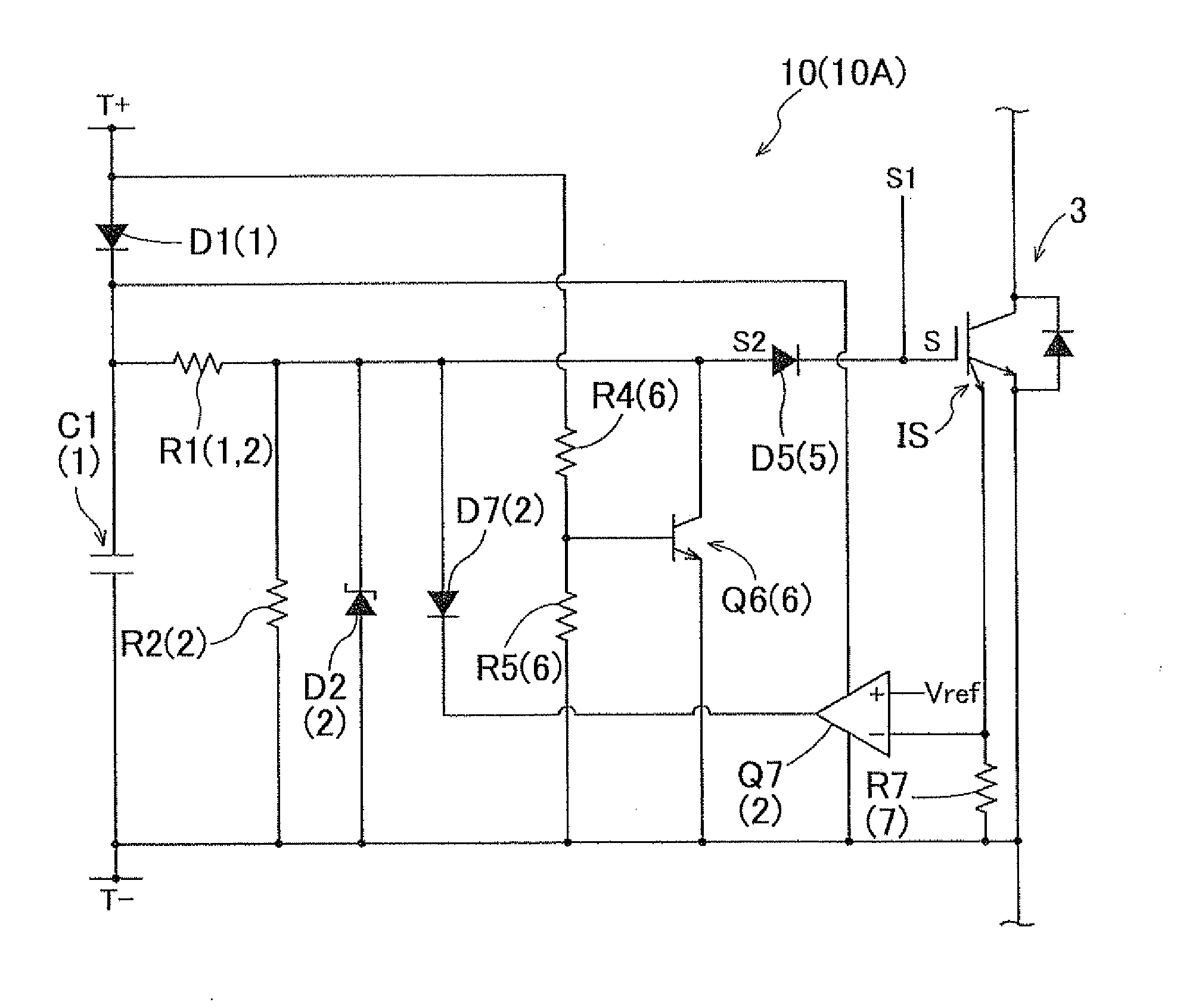
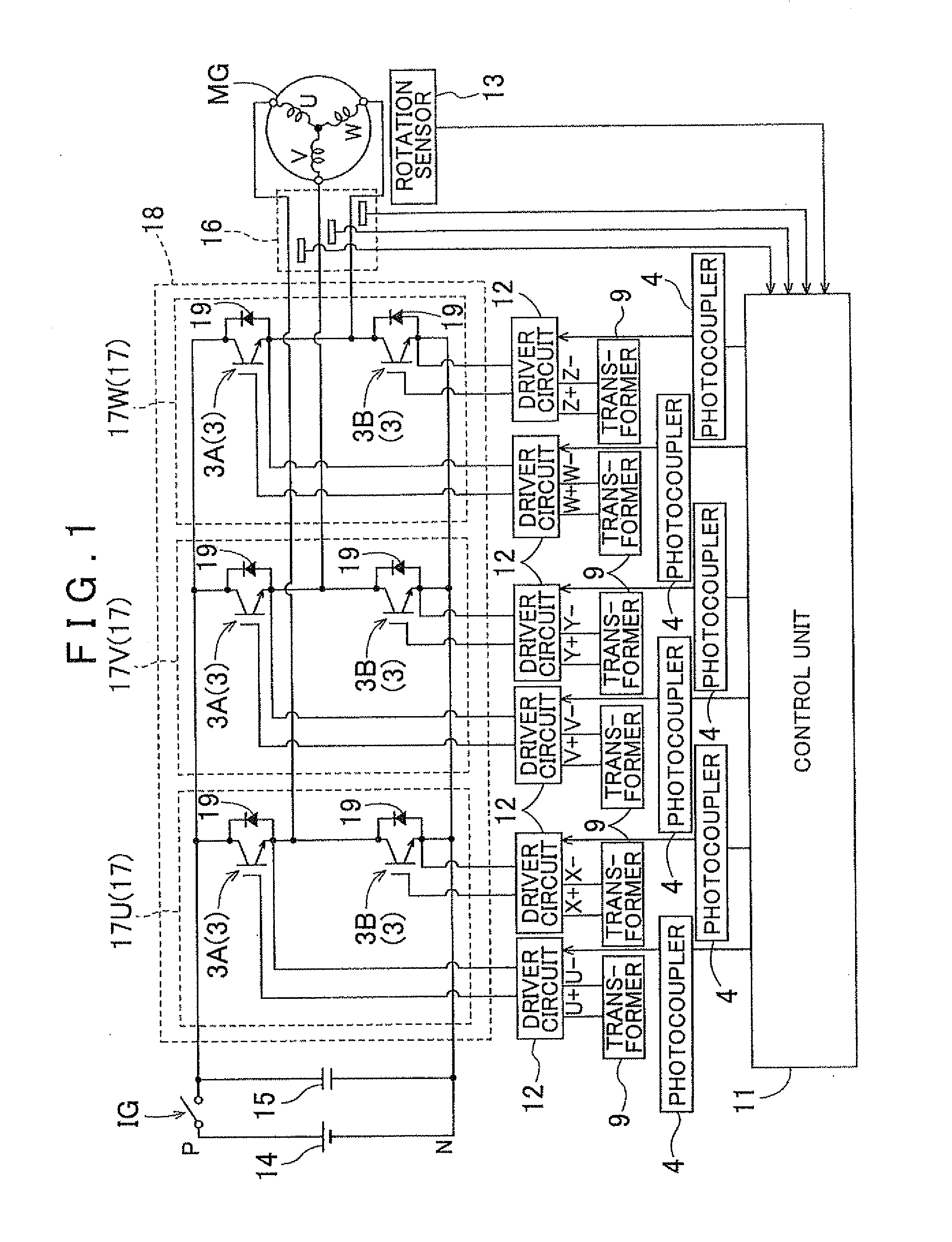
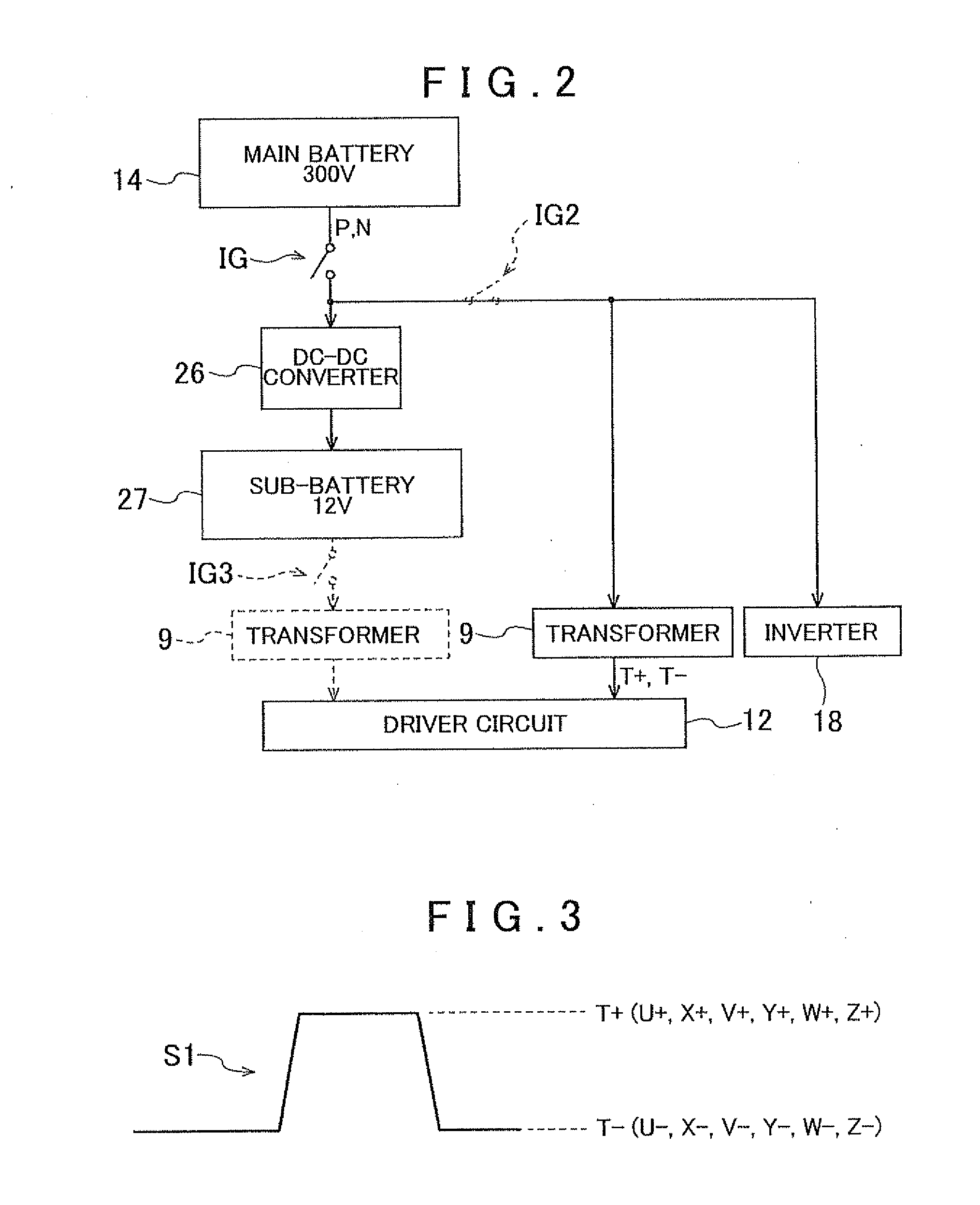
[0017]An embodiment of a case in which the present invention is applied to a motor driving circuit of an electric automobile or a hybrid automobile will be described below on the basis of the drawings. FIG. 1 shows a motor driving circuit to which a discharge control circuit according to the present invention is applied. In the interests of visibility, the discharge control circuit according to the present invention is not shown in FIG. 1. Note that a motor (rotating electric machine) MG naturally also functions as a generator. As shown in FIG. 1, a motor driving apparatus includes an inverter 18 that performs power conversion between direct current power and alternating current power, a direct current main battery (main power supply) 14, and a smoothing capacitor 15 interposed between the inverter 18 and the main battery 14 to smooth the direct current power. The main battery 14 is a chargeable secondary battery that supplies direct current power to the inverter 18 during a power r...


PUM


Abstract

A discharge control apparatus for discharging a residual charge that accumulates in a smoothing capacitor interposed between a direct current main power supply and an inverter, which performs a voltage conversion between a direct current power and an alternating current power, and remains in the smoothing capacitor when a connection between the inverter and the main power supply is cut, the discharge control apparatus. The discharge control apparatus having a backup power supply and a discharge control unit that is provided independently of a driver circuit for applying a switching control signal to a switching element constituting the inverter in order to operate the switching element in a saturation region, and that generates a discharge control signal for operating the switching element in an active region and applies the generated discharge control signal to the switching element.

Description

INCORPORATION BY REFERENCE[0001]The disclosure of Japanese Patent Application No. 2010-068757 filed on Mar. 24, 2010 including the specification, drawings and abstract is incorporated herein by reference in its entirety.BACKGROUND OF THE INVENTION[0002]The present invention relates to a discharge control apparatus for discharging a residual charge that accumulates in a smoothing capacitor interposed between an inverter and a direct current main power supply and remains in the smoothing capacitor when a connection between the inverter and the main power supply is cut.DESCRIPTION OF THE RELATED ART[0003]In an electric automobile driven by a rotating electric machine or a hybrid automobile driven by an internal combustion engine and a rotating electric machine, the rotating electric machine functioning as a motor is driven by converting direct current power supplied from a battery into alternating current power using an inverter. When the rotating electric machine functions as a genera...

Claims


Application Information

Patent Timeline
Patent Type & Authority Applications(United States)
IPC IPC(8): H02J7/04
CPCH02M1/08H02M2001/322H02M7/53871H02M1/322
Inventor NAKAMURA, YASUSHIAOKI, KAZUO
Owner AISIN AW CO LTD
Why Eureka
Try Eureka