Head-mounted display device

a display device and head-mounted technology, applied in the field of head-mounted display devices, can solve the problems of large distortion in the captured image, difficult to avoid, and wearers are likely to contact the surroundings, and achieve the effect of preventing contact with an obstacl

Inactive Publication Date: 2011-09-29
FUJIFILM CORP
View PDF0 Cites 80 Cited by
  • Summary
  • Abstract
  • Description
  • Claims
  • Application Information

AI Technical Summary

Benefits of technology

[0019]According to the above-mentioned aspects of the invention, the left and right cameras, each having a wide-angle lens, capture the image of a real space and each viewpoint image. A main image and a peripheral sub-image of the main image are extracted from each viewpoint image. The distortion of the wide-angle lens is corrected i

Problems solved by technology

Therefore, when the wearer moves with the HMD worn on the head, the wearer is likely to contact the surroundings, particularly, an obstacle disposed in the left-right direction deviating from the visual field due to the influence of the limit of the visual field.
However, in JP-A-2004-233948 in which a portion of the HMD is moved, in many cases, it is difficult t

Method used


Image

  • Head-mounted display device
  • Head-mounted display device
  • Head-mounted display device

Examples


first embodiment

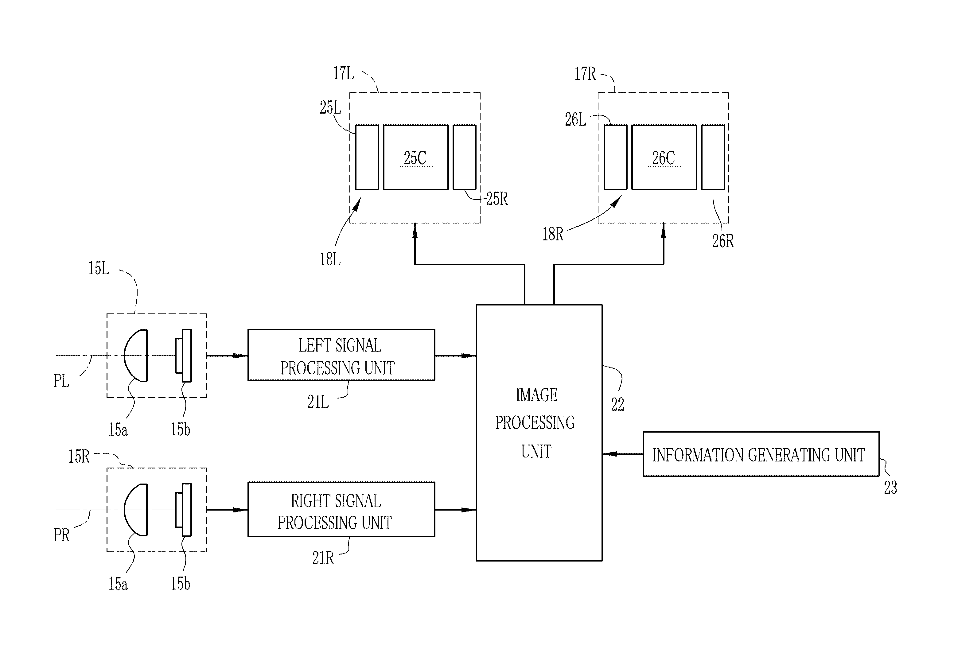
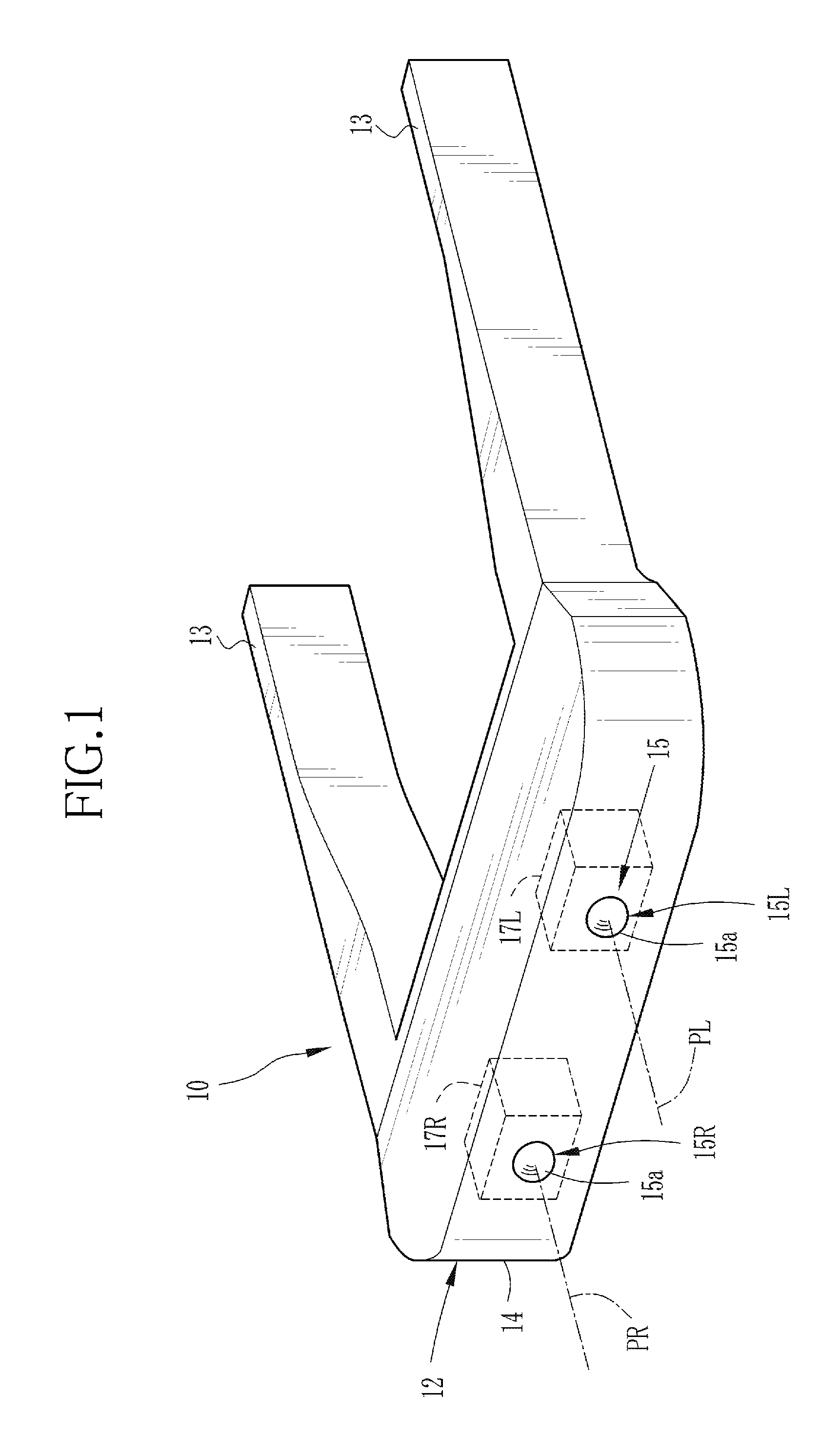
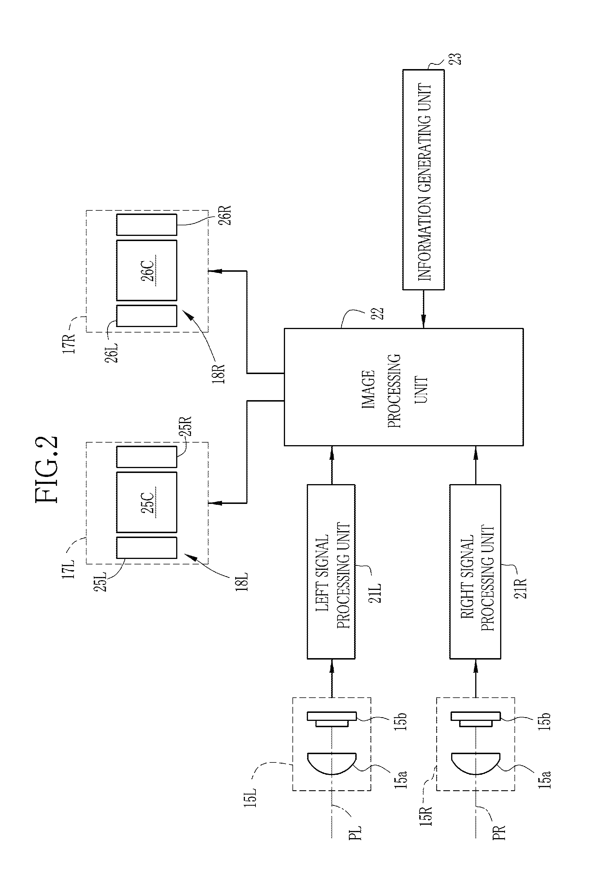
[0031]FIG. 1 shows the outward appearance of an HMD (head-mounted display device) according to an embodiment of the invention. An HMD 10 has a goggle shape and includes an anterior eye unit 12 and a pair of temples (bows) 13 that is provided integrally with the anterior eye unit 12. The HMD 10 is worn on the head of the user using the temples 13. The anterior eye unit 12 includes a box-shaped housing 14 that is provided so as to cover the front of the eyes of the wearer, a camera unit 15, and left and right display units 17L and 17R and various kinds of image processing circuits that are provided in the housing 14.

[0032]The camera unit 15 includes a left camera 15L and a right camera 15R. Each of the cameras 15L and 15R includes an imaging lens 15a. The imaging lenses 15a are arranged in the horizontal direction on a front surface of the housing 14 in front of the left and right eyes. The imaging lenses 15a are arranged such that a gap between optical axes PL and PR thereof is subst...

second embodiment

[0065]A second embodiment in which the display of the main image is switched between the 3D mode and the 2D mode according to the motion of the head of the wearer will be described below. Structures other than the following structure are the same as those in the first embodiment. Substantially the same components are denoted by the same reference numerals and a description thereof will be omitted.

[0066]In this embodiment, as shown in FIG. 5, a motion sensor 41, a mode control unit 42, and a selector 43 are provided. The motion sensor 41 is, for example, an acceleration sensor or an angular rate sensor, and detects the motion of the head of the wearer. In addition to the motion (for example, the rotation or linear motion) of the head of the wearer, the motion of the wearer accompanying the movement of the head is detected as the motion of the head.

[0067]The detection result of the motion sensor 41 is transmitted to the mode control unit 42. The mode control unit 42 determines the dis...

third embodiment

[0073]A third embodiment in which the display of the main image is changed to the 3D mode or the 2D mode according to the movement of the viewpoint of the wearer will be described below. Structures other than the following structure are the same as those in the second embodiment. Substantially the same components are denoted by the same reference numerals and a description thereof will be omitted.

[0074]In this embodiment, as shown in FIG. 7, a viewpoint sensor 44 is provided in an HMD 10. The viewpoint sensor 44 includes, for example, an infrared ray emitting unit that emits infrared rays to an eyeball of the wearer and a camera that captures the image of the eyeball, and a viewpoint is detected by using a known corneal reflection method. The viewpoint may be detected by other methods.

[0075]The mode control unit 42 controls the selector 43 on the basis of the detection result of the viewpoint sensor 44 to change the display mode of the HMD 10 between the 3D mode and the 2D mode. As ...


PUM


Abstract

An HMD includes left and right camera units which have wide-angle lenses, capture the image of a real space, and capture a left viewpoint image and a right viewpoint image. A main image is extracted from a central portion of each viewpoint image, and a left sub-image and a right sub-image are extracted from a peripheral portion of each viewpoint image. The distortion of the wide-angle lens in each main image is corrected, and the corrected main images are displayed in front of the left and right eyes as a stereo image. The left sub-image and the right sub-image are displayed on the left and right sides of the main image without being corrected.

Description

BACKGROUND OF THE INVENTION[0001]1. Field of the Invention[0002]The present invention relates to a head-mounted display device that is worn on a head of a wearer such that the wearer can view an image.[0003]2. Description of the Related Art[0004]A head-mounted display device (hereinafter, referred to as an HMD) is known which is worn on a head of a wearer and displays a video in front of eyes of the wearer. The HMD is used for various purposes. One of the purposes of the HMD is to display various kinds of additional information (hereinafter, referred to as AR information) superimposed on a real space (external scene), thereby providing information. For example, a light transmissive HMD and a video see-through HMD are used for the purpose. In the light transmissive HMD, the real space and the AR information displayed on liquid crystal are superimposed by, for example, a half mirror such that they can be observed by the user. In the video see-through HMD, a video camera captures the i...

Claims


Application Information

Patent Timeline
IPC IPC(8): G06T15/00G09G5/00
CPCG02B27/017H04N13/0468G02B2027/0123G02B2027/0134G02B2027/0138G02B2027/014G06F3/14G06T19/006G09G3/3666G09G2300/026G09G2340/10G09G2370/04G09G2370/16H04N5/3572H04N13/0007H04N13/0033H04N13/004H04N13/007H04N13/044H04N13/0454G02B2027/011H04N13/344H04N13/156H04N13/183H04N13/144H04N13/366H04N13/359H04N13/106H04N23/63H04N25/61
Inventor ENDO, HIROSHI
Owner FUJIFILM CORP
Why Eureka
Try Eureka