High voltage inverter device

a high-voltage inverter and high-voltage technology, applied in the direction of power conversion systems, efficient power electronics conversion, climate sustainability, etc., can solve the problem that the voltage cannot be boosted any more, and achieve the effect of stable and safe operation

Active Publication Date: 2011-09-29
RICOH KK
View PDF13 Cites 12 Cited by
  • Summary
  • Abstract
  • Description
  • Claims
  • Application Information

AI Technical Summary

Benefits of technology

[0033]With the high voltage inverter device according to the invention, a high-power high voltage can be continuously, stably, and safely obtained using the above-described configuration.

Problems solved by technology

Further, these devices are intended to utilize the magnetic flux density of the transformers as much as possible, but when further boosting the voltage, the magnetic flux density saturates, causing a problem that the voltage cannot be boosted any more.

Method used


Image

  • High voltage inverter device
  • High voltage inverter device
  • High voltage inverter device

Examples


first embodiment

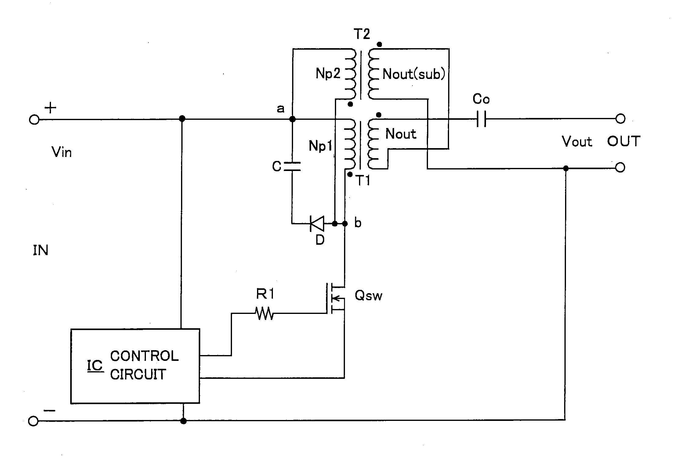
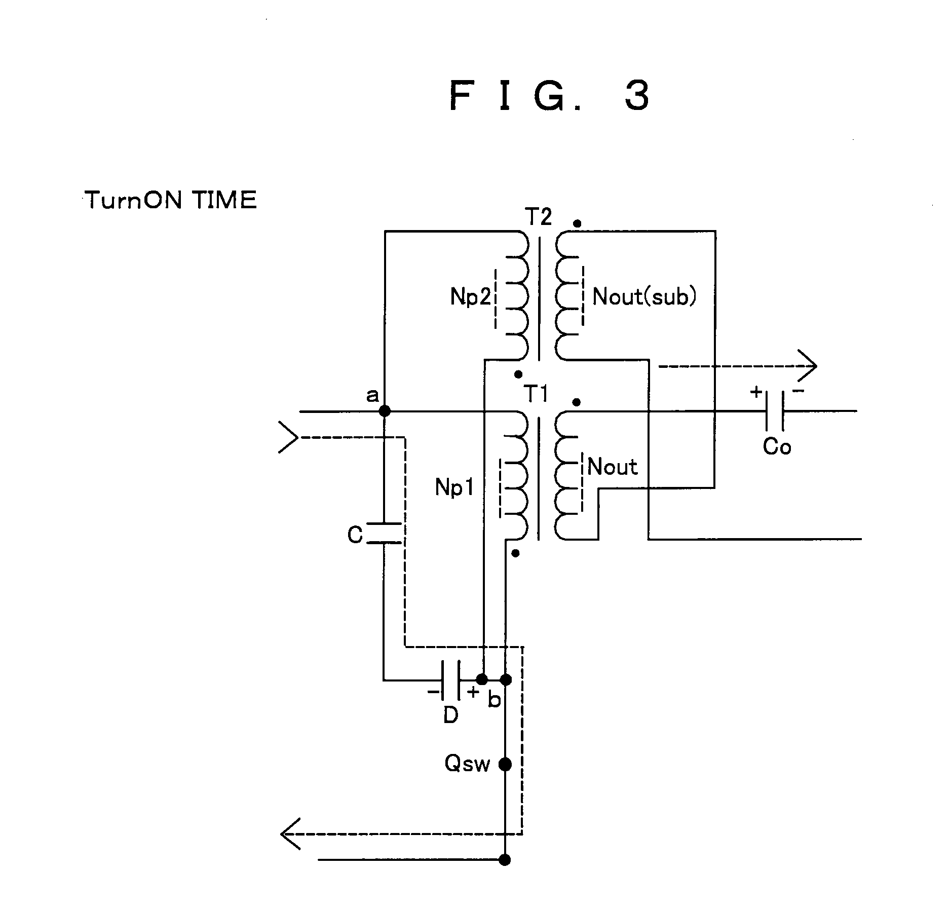
[0049]A first embodiment (an example of parallel excitation and voltage addition) of a high voltage inverter device according to the invention will be described with reference to FIG. 1. FIG. 1 is a circuit diagram illustrating its configuration in which IN denotes an input terminal and OUT denotes an output terminal (this applies to the following embodiments).

[0050]This high voltage inverter device receives, as an input voltage Vin, a DC voltage (60 V or less) or a voltage within SELV (Safety Extra Low Voltage) composed of a DC component with a pulsating flow superposed thereon which is supplied through the input terminal IN, switches the input voltage Vin by a switching element Qsw to pass exciting current to excitation windings Np1, Np2 on the primary side of a first transformer T1 and a second transformer T2, and outputs high voltages from output windings Nout, Nout(sub) on the secondary side of the transformers T1, T2 to output an output voltage Vout being an AC high voltage fr...

second embodiment

[0064]Next, a second embodiment (an example of parallel excitation and current addition) of a high voltage inverter device according to the invention will be described with reference to FIG. 8. FIG. 8 is a circuit diagram illustrating its configuration.

[0065]In the second embodiment, the output windings Nout, Nout(sub) of the separate first and second transformers T1, T2 having the same characteristics are connected in parallel such that outputs thereof are subjected to current addition, and connected to the output terminal OUT side. According to this embodiment, though the output voltage is substantially the same as the case of one transformer, the output current can be doubled so that the output power can also be doubled.

[0066]That the excitation windings Np1, Np2 of the transformers T1, T2 are connected in parallel between the positive electrode of the input power supply and the positive electrode of the switching element Qsw is the same with the first embodiment. The other confi...

third embodiment

[0067]Next, a third embodiment (an example of split excitation and current addition) of a high voltage inverter device according to the invention will be described with reference to FIG. 9. FIG. 9 is a circuit diagram illustrating its configuration.

[0068]In the third embodiment, the excitation windings Np1, Np2 of the separately provided first and second transformers T1, T2 having the same characteristics are connected in series between the positive electrode of the input power supply and the positive electrode of the switching element Qsw. Between the positive electrode of the input power supply and the positive electrode of the switching element Qsw, a series circuit composed of a diode D and a capacitor C constituting a snubber circuit is also connected.

[0069]The output windings Nout, Nout(sub) of the first and second transformers T1, T2 are connected in parallel such that outputs thereof are subjected to current addition, and connected to the output terminal OUT side as in the s...


PUM


Abstract

The high voltage inverter device receives, as an input voltage, a DC voltage or a voltage within Safety Extra Low Voltage composed of a DC component with a pulsating flow superposed thereon. The input voltage is switched by a switching element to pass an exciting current to excitation windings on a primary side of a plurality of separate transformers having same characteristics to simultaneously excite the excitation windings. Output windings of the plurality of transformers are connected in parallel or in series with one another, and time axes of waveforms of output voltages of the output windings are synchronized. Thereby, a high-power high voltage is outputted continuously, stably, and safely from both ends of the output windings connected in parallel or in series.

Description

BACKGROUND OF THE INVENTION[0001]1. Field of the Invention[0002]The invention relates to a high voltage inverter device such as a switching regulator, an inverter or the like used in a high voltage power supply unit, a power supply unit for discharge or the like.[0003]2. Description of the Related Art[0004]Atmospheric pressure plasma is applied to various industrial products as a means for surface treatment for improvement of surface quality, removal of contamination or the like. In the case where adhesion, printing, coating or the like is applied to a resin of the like, performing pre-treatment using the atmospheric pressure plasma can improve the wettability thereof.[0005]For example, when trying to coat a printed matter which has been printed with a resin toner by an electrophotographic image forming apparatus with an ultraviolet cure varnish, the varnish on a part printed with the resin toner may be rejected due to a wax component contained in the resin toner. However, performin...

Claims


Application Information

Patent Timeline
Patent Type & Authority Applications(United States)
IPC IPC(8): H02M7/537
CPCH02M7/48Y02B70/1441H02M2007/4815H02M7/4815Y02B70/10
Inventor KAMATA, HISAHIRO
Owner RICOH KK
Why Eureka
Try Eureka