X-ray generating apparatus and control method thereof

a technology of generating apparatus and generating beam, which is applied in the direction of electrical apparatus, basic electric elements, electric discharge tubes, etc., can solve the problems of low voltage and unnecessary beam radiation, and achieve the effect of suppressing the generation of unnecessary x-ray

Inactive Publication Date: 2011-09-29
CANON KK
View PDF5 Cites 9 Cited by
  • Summary
  • Abstract
  • Description
  • Claims
  • Application Information

AI Technical Summary

Benefits of technology

[0010]The present invention provides technology that enables suppression of the generation of an unnecessary X-ray without changing the size or weight of an X-ray tube.

Problems solved by technology

Therefore, immediately after starting voltage application, the voltage is low, so the electron beam is also radiated to an unnecessary area.

Method used


Image

  • X-ray generating apparatus and control method thereof
  • X-ray generating apparatus and control method thereof
  • X-ray generating apparatus and control method thereof

Examples


embodiment 1

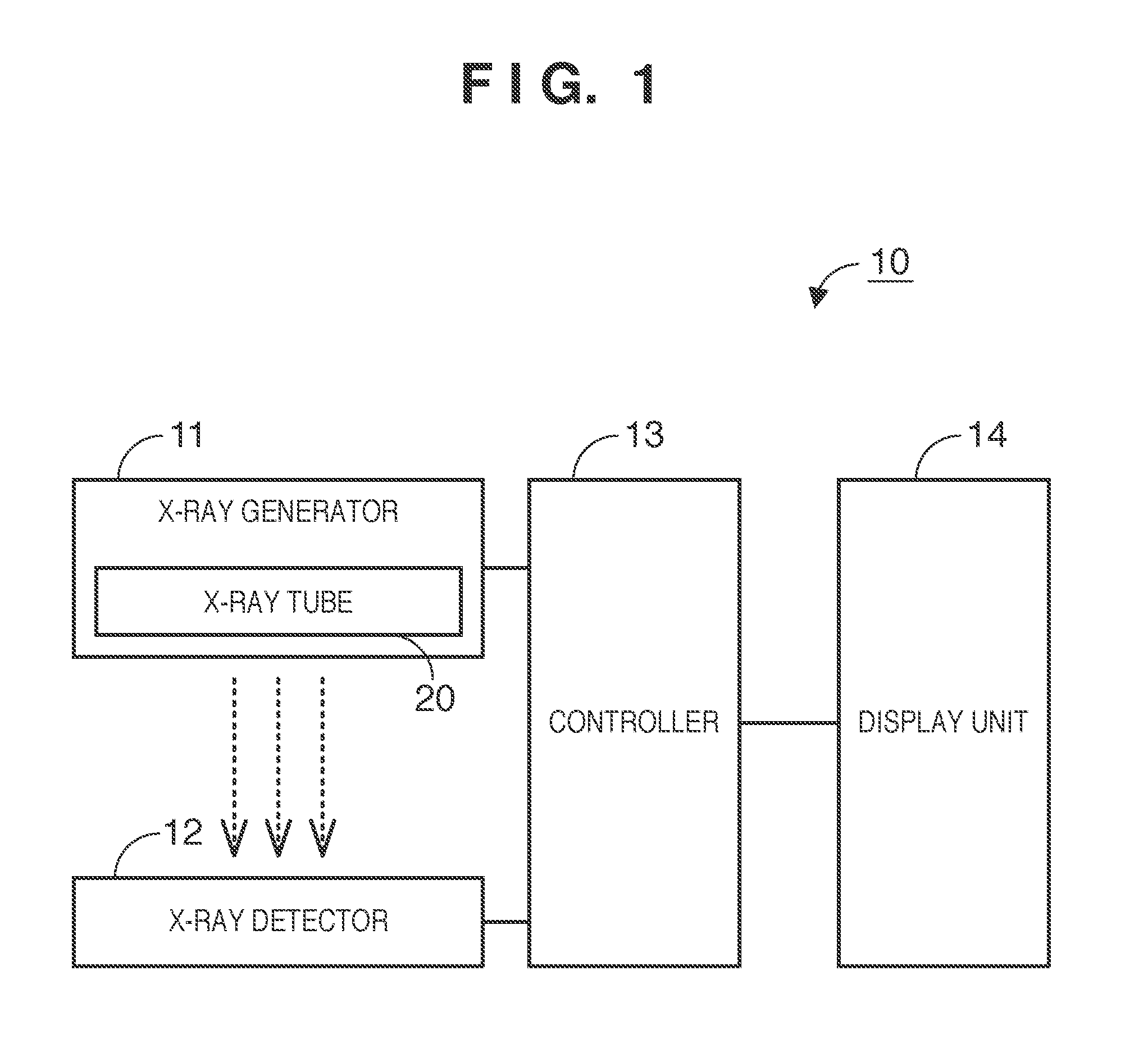
[0026]FIG. 1 shows an example of the functional configuration of a radiography apparatus 10 according to one embodiment of the present invention.

[0027]The radiography apparatus 10 is configured including one or a plurality of computers. Provided in the computer are, for example, a main controller such as a CPU, and storage units such as a ROM (Read Only Memory) and a RAM (Random Access Memory). The computer may also be provided with a communications unit such as a network card, and input / output units such as a keyboard, a display, or a touch panel. Each of these constituent units is connected via a bus or the like, and is controlled by the main controller executing a program stored in a storage unit.

[0028]Here, the radiography apparatus 10 is configured including an X-ray generator 11, an X-ray detector 12, a controller 13, and a display unit 14.

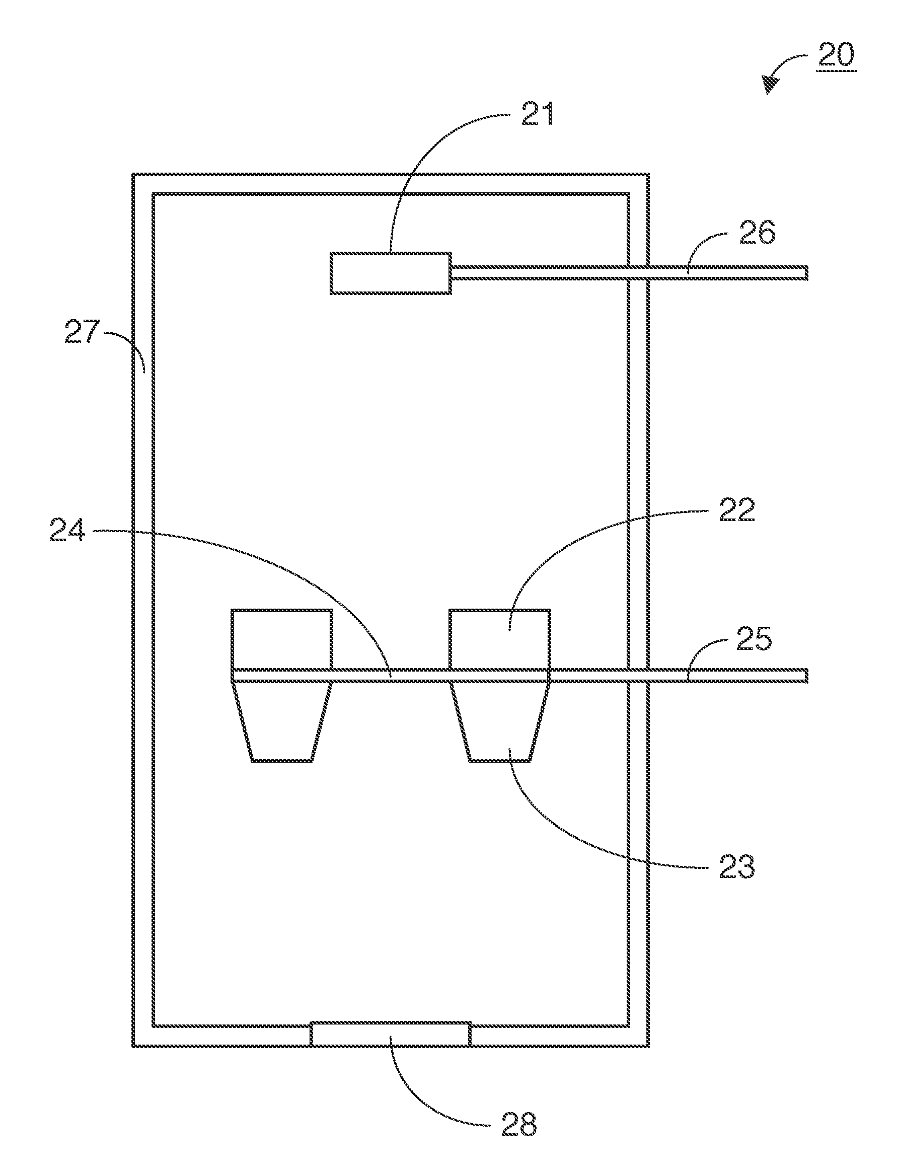
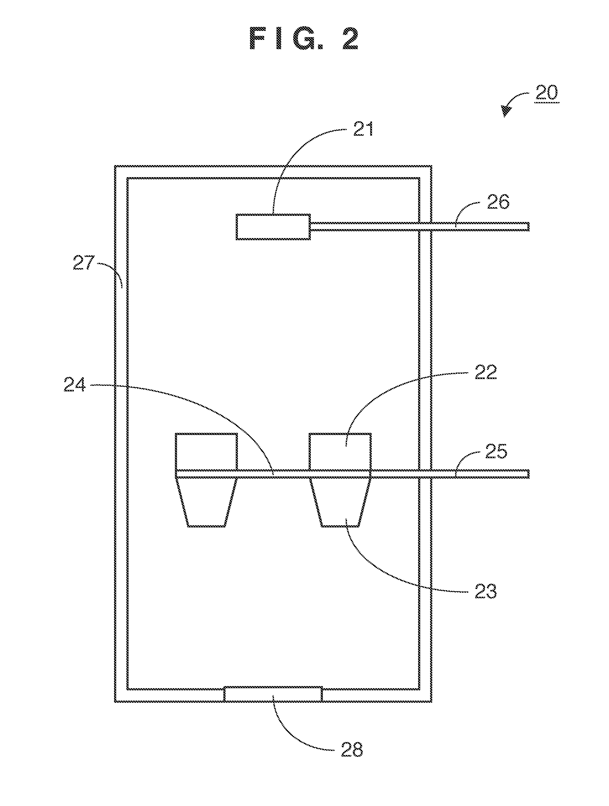
[0029]The X-ray generator 11 fulfills a role of irradiating an X-ray toward a subject (for example, a person). An X-ray tube 20 that genera...

embodiment 2

[0051]Next is a description of Embodiment 2. FIG. 4 shows an example configuration of an X-ray tube 20 according to Embodiment 2. Aspects of the configuration that are the same as in FIG. 2 illustrating Embodiment 1 are assigned the same reference numbers, and a description thereof may be omitted here.

[0052]In the X-ray tube 20 according to Embodiment 2, a lens electrode 30 is provided between an electron source 21 and a rear shield member 22. The lens electrode 30 forms an electron beam irradiated from the electron source 21 by operation of a lens. A first voltage that is a voltage that does not cause lens operation, and a second voltage that is a voltage that causes lens operation, are applied to the lens electrode 30. More specifically, the first voltage is a voltage lower than the voltage applied to the electron source 21, and the second voltage is a voltage higher than the voltage applied to the electron source 21.

[0053]Next is a description of an example of control of operatio...

embodiment 3

[0060]Next is a description of Embodiment 3. The configuration of an X-ray tube 20 according to Embodiment 3 is the same as in FIG. 4 illustrating Embodiment 2, so a description thereof is omitted here. Below, points that differ from Embodiment 2 will be described. Among differing points are the time when electrons are emitted by the electron source 21, and the time when a voltage is applied to the lens electrode 30.

[0061]An example of control of operation of the X-ray tube 20 according to Embodiment 3 will be described with reference to FIG. 6.

[0062]The controller 13 applies the second voltage to the lens electrode 30 at the time T12. That is, application of the second voltage to the lens electrode 30 is performed after the transmission-type target 24 has reached the predetermined voltage at the time T2, and prior to emission of electrons from the electron source 21 at the time T10.

[0063]When stopping X-ray generation, the controller 13 stops emission of electrons by the electron s...


PUM


Abstract

An X-ray generating apparatus controls driving of an X-ray tube. The X-ray tube includes an electron source emitting electrons due to application of a voltage, a transmission-type target generating an X-ray due to collision of electrons emitted from the electron source, and a shield member disposed between the electron source and the transmission-type target, the shield member having an opening that electrons emitted from the electron source pass through, and blocking an X-ray that scatters toward the electron source. When generating the X-ray, application of a voltage to the transmission-type target is started, and emission of electrons from the electron source is caused after passage of a predetermined period indicating a time period from starting voltage application until the transmission-type target reaches a predetermined voltage. When stopping X-ray generation, application of the voltage to the transmission-type target is stopped after stopping the emission of electrons from the electron source.

Description

BACKGROUND OF THE INVENTION[0001]1. Field of the Invention[0002]The present invention relates to an X-ray generating apparatus and a control method thereof.[0003]2. Description of the Related Art[0004]Among X-ray tubes, there are X-ray tubes that employ a reflecting-type target and those that employ a transmission-type target. In either type of X-ray tube, a target is irradiated with an electron beam that has been accelerated to high speed, and thus an X-ray is generated from the irradiated area. At this time, X-rays are emitted in all directions. Therefore, in many X-ray tubes, in order to block an X-ray travelling in a direction other than that which is necessary, an X-ray shield member of lead or the like is used to cover a chamber into which the X-ray tube has been inserted or an area surrounding the X-ray tube. In Japanese Patent Laid-Open No. 2007-265981, technology is disclosed in which emission of an X-ray in a direction other than that which is necessary, is suppressed by p...

Claims


Application Information

Patent Timeline
Patent Type & Authority Applications(United States)
IPC IPC(8): H05G1/32
CPCH01J35/08H01J35/16H05G1/32H01J2235/166H05G1/30H01J2235/087H01J35/116
Inventor OGURA, TAKAONOMURA, ICHIROUEDA, KAZUYUKITSUJII, OSAMU
Owner CANON KK
Why Eureka
Try Eureka