Electronic endoscope system and processor unit thereof, and method for obtaining blood vessel information

a technology of endoscopy and processor unit, which is applied in the field of imaging and endoscopy system, and the method of obtaining blood vessel information, can solve the problem of incorrect determination of oxygen saturation level based on the situation

Active Publication Date: 2011-09-29
FUJIFILM CORP
View PDF10 Cites 39 Cited by
  • Summary
  • Abstract
  • Description
  • Claims
  • Application Information

AI Technical Summary

Benefits of technology

[0021]According to the present invention, the three types of the narrow band light are in different wavelength bands from one another within 400 nm to 600 nm, and include at least one type of blue band illumination light and at least one type of green band illumination light. The three types of the narrow band light are applied to living tissue containing the blood vessel inside a body cavity. The image of the living tissue is captured during application of the illumination light, to obtain a plurality of narrow band signals that correspond to each type of the narrow band light in the different wavelength band. The blood vessel information including the depth of the blood vessel and the hemoglobin index is obtained based on the obtained plural narrow band signals. Thus, it is possible to precisely obtain the blood vessel information such as the hemoglobin index and an oxygen saturation level, in consideration of the depth of the blood vessel.
[0022]According to the present invention, information on the shallow or superficial blood vessel is obtained with the use of the first and second narrow blue band light, and information on the deep blood vessel is obtained with the use of the third narrow green band light. Therefore, it is possible to precisely obtain the hemoglobin index of the blood vessel lying in a shallow to relatively deep (at most 500 nm) depth, which is concerned in diagnosis.

Problems solved by technology

However, the U.S. Patent Application Publication No. 2003 / 0176768 does not describe determination of the hemoglobin index and the oxygen saturation level of the blood vessel, though describes the depth of the blood vessel.
Therefore, the determined oxygen saturation level could be incorrect depending on the depth of the blood vessel.

Method used


Image

  • Electronic endoscope system and processor unit thereof, and method for obtaining blood vessel information
  • Electronic endoscope system and processor unit thereof, and method for obtaining blood vessel information
  • Electronic endoscope system and processor unit thereof, and method for obtaining blood vessel information

Examples


first embodiment

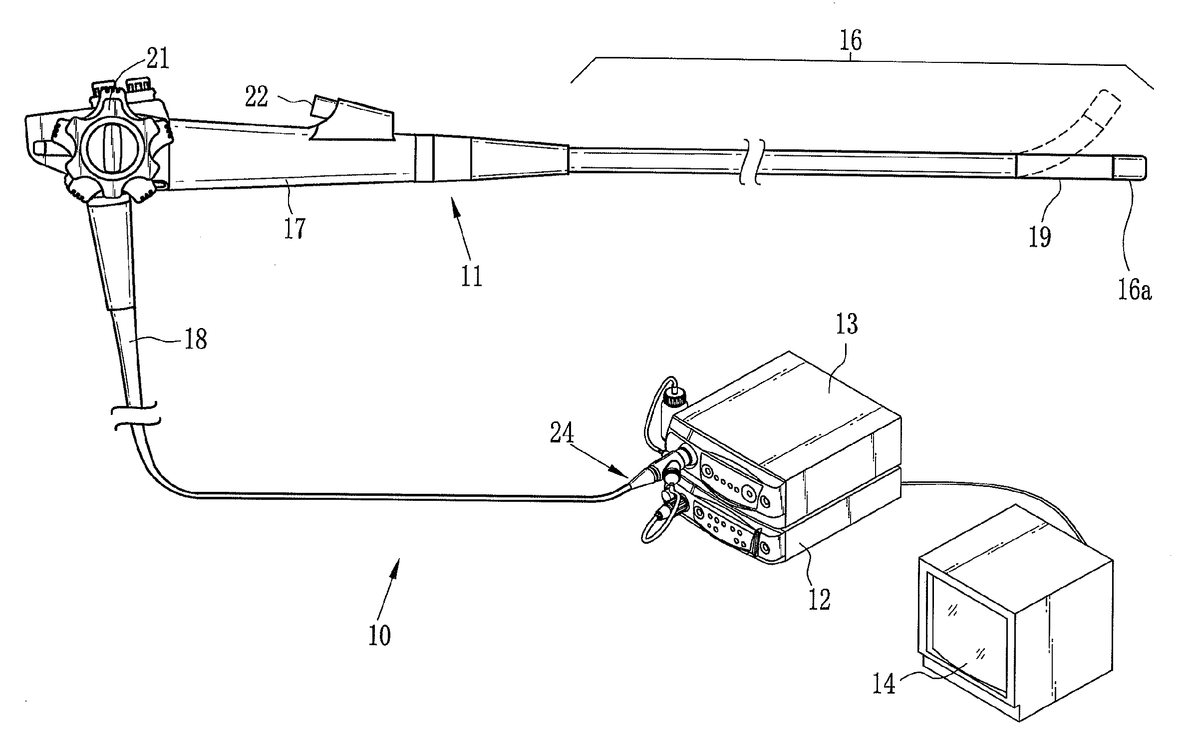
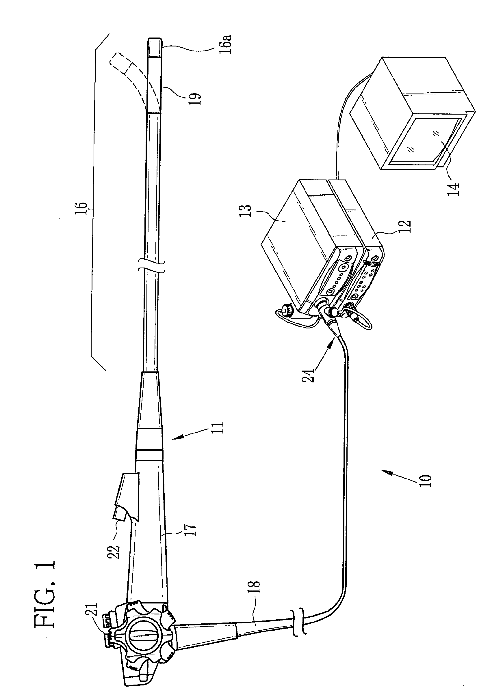
[0045]As shown in FIG. 1, an electronic endoscope system 10 according to a first embodiment is constituted of an electronic endoscope 11 for imaging the inside of a human body cavity, a processor unit 12 that produces an endoscope image from an image signal obtained by the electronic endoscope 11, a light source unit 13 that supplies the electronic endoscope 11 with light for lighting the inside of the body cavity, and a monitor 14 for displaying the endoscope image. The electronic endoscope 11 is provided with a flexible insert section 16 to be introduced into the human body cavity, an operation section 17 disposed at a proximal end of the insert section 16, and a universal cord 18 for connecting the operation section 17 to the processor unit 12 and the light source unit 13.

[0046]The insert section 16 has a bending portion 19 at its distal end. The bending portion 19 is composed of a train of joint pieces. The bending portion 19 flexibly bends up or down or from side to side in res...

second embodiment

[0087]In an electronic endoscope system 100 according to a second embodiment, as shown in FIG. 13, a CCD 90 is a color CCD having R, G, and B pixels. Furthermore, in the special light mode, the normal light NL is applied to the internal body part to be examined instead of the third special light L3, as shown in FIG. 14. The second brightness ratio R2 is calculated with use of an image signal that is obtained from the G pixels of the CCD 90 in application of the normal light NL. The electronic endoscope system 100 according to the second embodiment does not use the third special light L3, and hence does not have the third special light source. Since the other components of the electronic endoscope system 100 according to the second embodiment are substantially the same as those of the first embodiment, the description thereof will be omitted.

[0088]The R, G, and B pixels of the CCD 90 have R, G, and B color filters, respectively. Referring to FIG. 15, the R, G, and B color filters hav...

third embodiment

[0091]In a third embodiment, the first to fourth special light sources are not provided. Instead, an acoustic-optical tunable filter separates reflected light of the normal light NL into first to fourth special light L1 to L4. As shown in FIG. 16, an electronic endoscope system 110 according to the third embodiment is the same as the electronic endoscope system 10 of the first embodiment, except for provision of the acoustic-optical tunable filter 111 in the electronic endoscope 11 and elimination of the first to fourth special light sources 33 to 35 and 38.

[0092]The electronic endoscope 110 according to the third embodiment is provided with the acoustic-optical tunable filter 111 disposed between the imaging window 50 and the condenser lens 51. In the normal light mode, the acoustic-optical tunable filter 111 is not actuated, so that the normal light NL reflected from the internal body part to be examined is incident upon the CCD 44. In the special light mode, out of the normal lig...


PUM


Abstract

Ina special light mode, first to fourth special images are captured under first to fourth special light being narrow band light. A brightness ratio calculator extracts a blood vessel area containing a blood vessel from each special image. The brightness ratio calculator calculates first to fourth brightness ratios from the special images on every pixel within the blood vessel area. A depth and hemoglobin index calculator calculates the depth of the blood vessel and a hemoglobin index corresponding to the first and second brightness ratios, based on a correlation between the depth of the blood vessel and the hemoglobin index stored in advance. A depth and oxygen saturation calculator calculates an oxygen saturation level corresponding to the third and fourth brightness ratios, based on a correlation between the depth of the blood vessel and the oxygen saturation level stored in advance.

Description

BACKGROUND OF THE INVENTION[0001]1. Field of the Invention[0002]The present invention relates to an electronic endoscope system for imaging information about a blood vessel, a processor unit for an electronic endoscope, and a method for obtaining blood vessel information.[0003]2. Description Related to the Prior Art[0004]In a medical field, diagnosis and treatment with use of an electronic endoscope is widely carried out in recent years. The electronic endoscope is provided with a slender insert section to be introduced into a human body cavity. The insert section contains an image sensor such as a CCD at a distal end. The electronic endoscope is connected to a light source unit. Light from the light source unit is guided through the electronic endoscope, and is emitted from the distal end of the insert section to light the inside of the body cavity. While the inside of the body cavity is irradiated with the light, the image sensor captures an image of an internal body part to be ex...

Claims


Application Information

Patent Timeline
Patent Type & Authority Applications(United States)
IPC IPC(8): A61B1/04A61B5/1459A61B1/06
CPCA61B1/00009G06T2207/30101A61B1/00186A61B1/0051A61B1/05A61B1/0638A61B1/0669A61B1/07A61B5/1076A61B5/14551A61B5/1459A61B1/063A61B1/0646G06T2207/10068G06T5/50G06T7/0012G06T2207/20221G06T2207/20224A61B1/0005A61B1/000094A61B1/0655
Inventor YAMAGUCHI, HIROSHI
Owner FUJIFILM CORP
Why Eureka
Try Eureka