Installation structure of solar cell module

a solar cell module and installation structure technology, applied in the direction of solar heat collector mounting/support, solar heat collector safety, light and heating apparatus, etc., can solve the problems of time and effort expended for maintenance or the like, increase the cost, etc., to reduce the overall cost of the roof including the structural member, the effect of preventing rainwater or the like from entering simplifying the water resistance on the side of the structural member

Inactive Publication Date: 2011-10-06
YANEGIJUTSUKENKYUJO CO LTD
View PDF43 Cites 81 Cited by
  • Summary
  • Abstract
  • Description
  • Claims
  • Application Information

AI Technical Summary

Benefits of technology

[0038]According to the present invention, a waterproof member is arranged between the eaves-side frame in the solar cell module on the ridge side and the ridge-side frame of the solar cell module on the eaves side and therefore, infiltration of rain water or the like to the side of the structural member from between the eaves-side frame and the ridge-side frame can be prevented. Because infiltration of rain water or the like to th...

Problems solved by technology

However, a plurality of solar cell modules to be installed on a roof is successively fixed to the sheathing roof board from the eaves side of the roof toward the ridge side according to a conventional installation structure of solar cell modules and thus, while installation work of solar cell modules is simplified, when s...

Method used


Image

  • Installation structure of solar cell module
  • Installation structure of solar cell module
  • Installation structure of solar cell module

Examples


Embodiment Construction

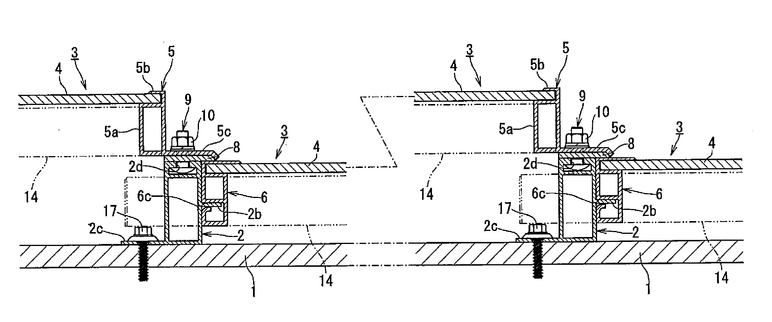
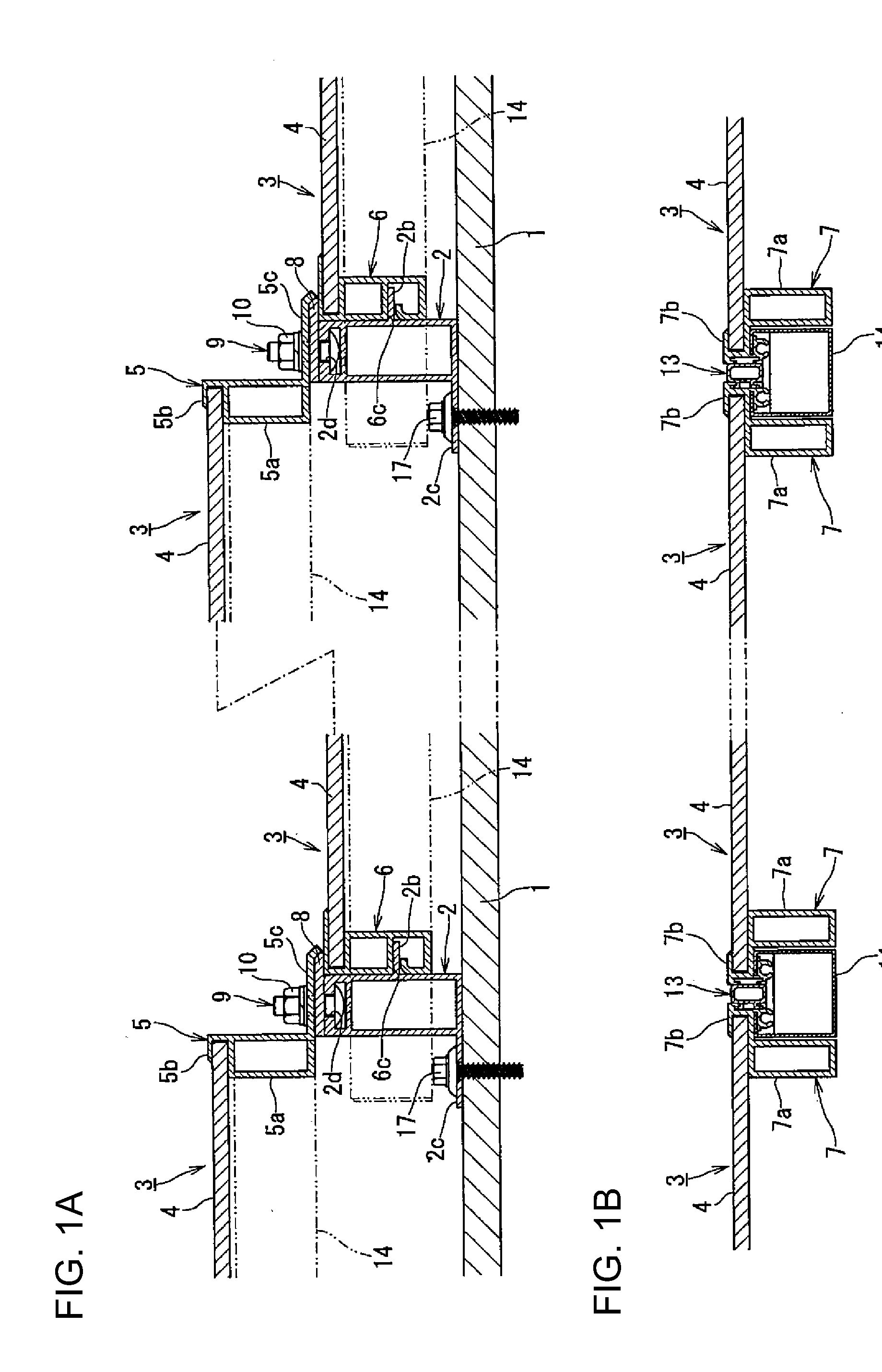
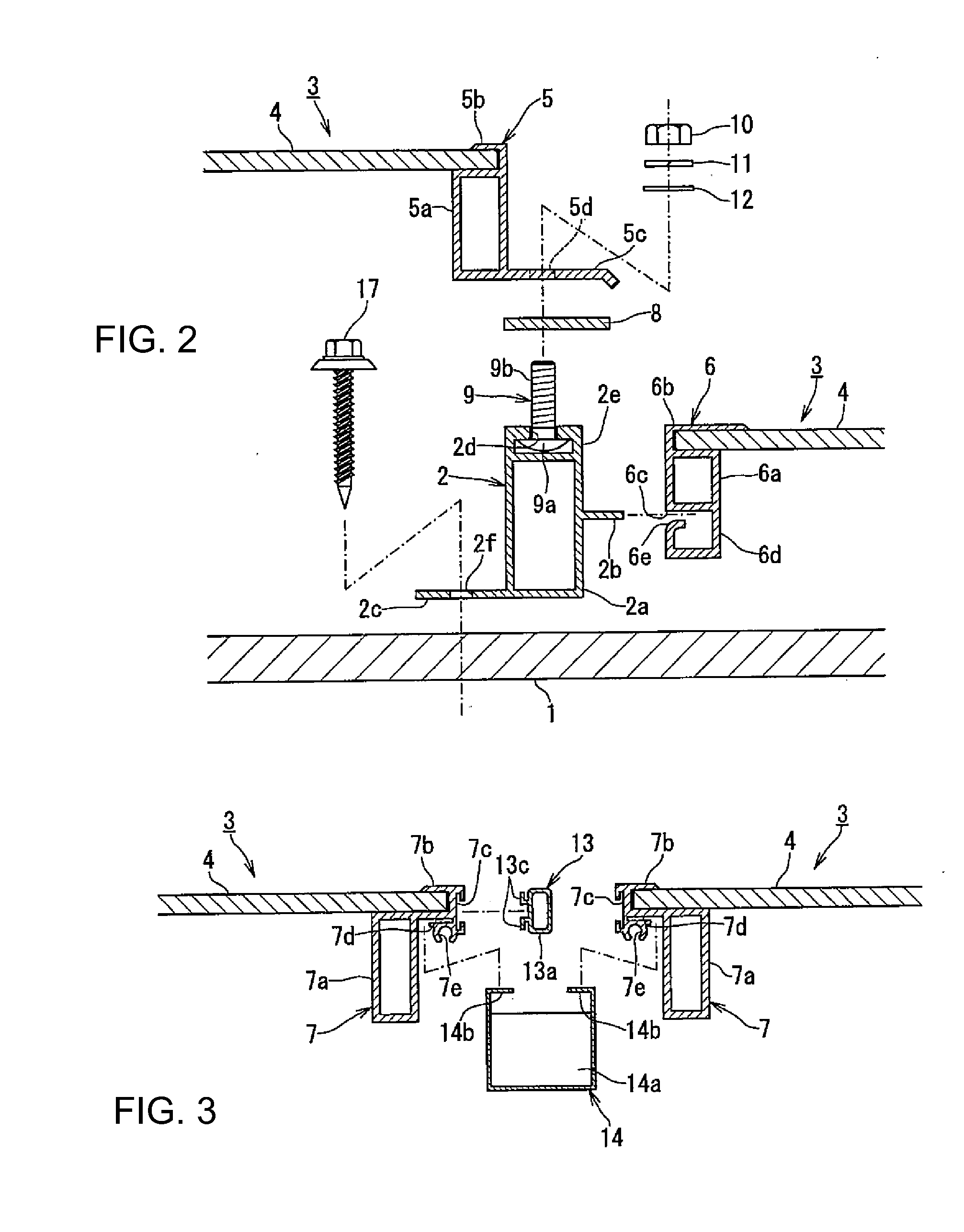
[0055]An installation structure of a solar cell module that is a preferred embodiment of the present invention will be described below in detail with reference to FIGS. 1 to 4. FIG. 1A is a sectional view showing an installation structure of a solar cell module in the present invention by cutting the installation structure in a direction linking the ridge side and the eaves side of a roof and FIG. 1B is a sectional view showing the installation structure of a solar cell module by cutting the installation structure in FIG. 1A in a direction perpendicular to the direction linking the ridge side and the eaves side of the roof. FIG. 2 is an exploded sectional view showing the installation structure shown in FIG. 1A by breaking down the installation structure into each member. FIG. 3 is an exploded sectional view showing the installation structure shown in FIG. 1B by breaking down the installation structure into each member. FIG. 4 is a ridge-side side view showing a joint part of a sola...


PUM


Abstract

An installation structure of a solar cell module comprising: a solar cell module including a solar panel, an eaves-side frame in a long shape holding an edge on an eaves side, a ridge-side frame in a long shape holding an edge on a ridge side opposite to the edge on the eaves side, and a lateral frame in a long shape holding edges of the solar panel different from the above edges; and a fixing member fixed to a predetermined structural member in a roof at a position on a ridge side further than the ridge-side frame and configured to prevent the ridge-side frame from moving towards the ridge side of the roof and in a direction perpendicular to a surface of the solar panel, the eaves-side frame of another solar cell module being positioned above the ridge-side frame and supported by the fixing member from outside.

Description

BACKGROUND OF THE INVENTION[0001]1. Field of the Invention[0002]The present invention relates to an installation structure of a solar cell module to install the solar cell module on a roof or the like.[0003]2. Description of the Related Art[0004]Photovoltaic power generation by installing a plurality of solar cell modules obtained by enclosing an outer circumference of plate-shaped solar panels with frames has been known.[0005]As an installation structure of a solar cell module, for example, a fastening part to fasten to a sheathing roof board and a fitting recess are formed in a ridge-side frame to hold a ridge side of a solar panel, a fitting convex to fit into the fitting recess of the ridge-side frame is formed in an eaves-side frame to hold an eaves side of the solar panel and, while the fastening part of the ridge-side frame in solar cell modules placed facing each other on the eaves side is fixed to the sheathing roof board, solar cell modules on the eaves and ridge sides are...

Claims


Application Information

Patent Timeline
IPC IPC(8): E04D13/18E04D13/064E04B1/38E04B1/70
CPCF24J2/4614F24J2/5211F24J2/5245F24J2/5254F24J2/5258F24J2/5262H02S20/23F24J2002/467F24J2002/5294F24J2002/5296Y02B10/12Y02B10/20Y02E10/47F24J2002/0061F24S25/20F24S25/61F24S25/632F24S25/636F24S25/67F24S40/44F24S2020/13F24S2025/021F24S2025/022F24S2025/6007Y02B10/10Y02E10/50
Inventor TSUZUKI, JOJIKOBAYASHI, SHUICHIYAMAUCHI, KENJI
Owner YANEGIJUTSUKENKYUJO CO LTD
Why Eureka
Try Eureka