Hydraulic power transmission

a technology of hydroelectric transmission and transmission shaft, which is applied in the direction of rotary clutches, fluid couplings, gearings, etc., can solve the problem that insufficient oscillation damping effect cannot be obtained in many cases

Inactive Publication Date: 2011-10-06
AISIN AW CO LTD
View PDF0 Cites 47 Cited by
  • Summary
  • Abstract
  • Description
  • Claims
  • Application Information

AI Technical Summary

Benefits of technology

[0007]However, as the aforementioned hydraulic power transmission or the lockup device in the related art, even though the dynamic damper including a mass and a resilient member is coupled to the driven plate or the output plate as the output elements of the damper mechanism (a lockup damper mechanism), a sufficient oscillation damping effect cannot be obtained in many cases.

Problems solved by technology

However, as the aforementioned hydraulic power transmission or the lockup device in the related art, even though the dynamic damper including a mass and a resilient member is coupled to the driven plate or the output plate as the output elements of the damper mechanism (a lockup damper mechanism), a sufficient oscillation damping effect cannot be obtained in many cases.

Method used


Image

  • Hydraulic power transmission
  • Hydraulic power transmission
  • Hydraulic power transmission

Examples


Embodiment Construction

[0025]Subsequently, a mode for carrying out the present invention will be described using embodiments.

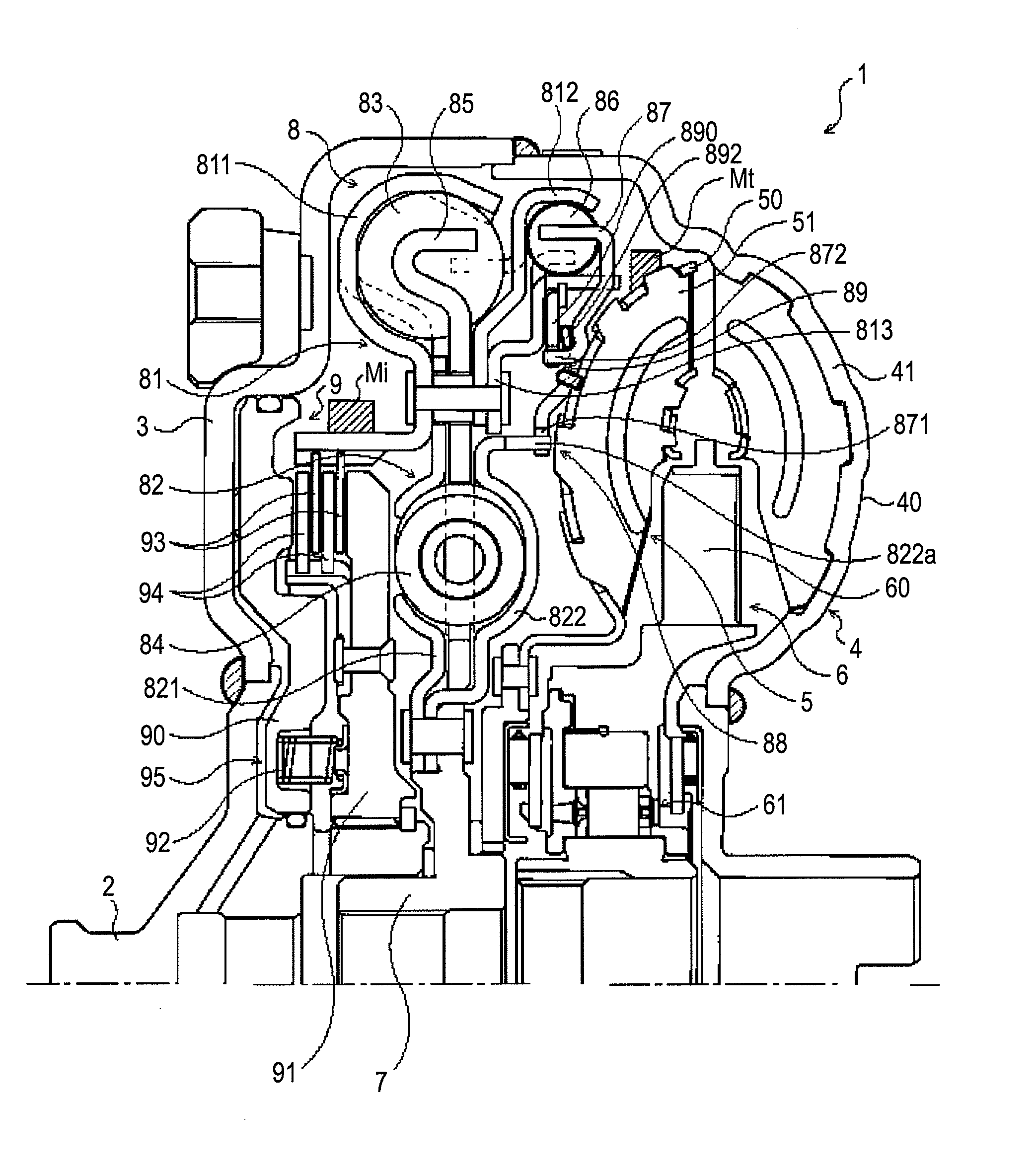
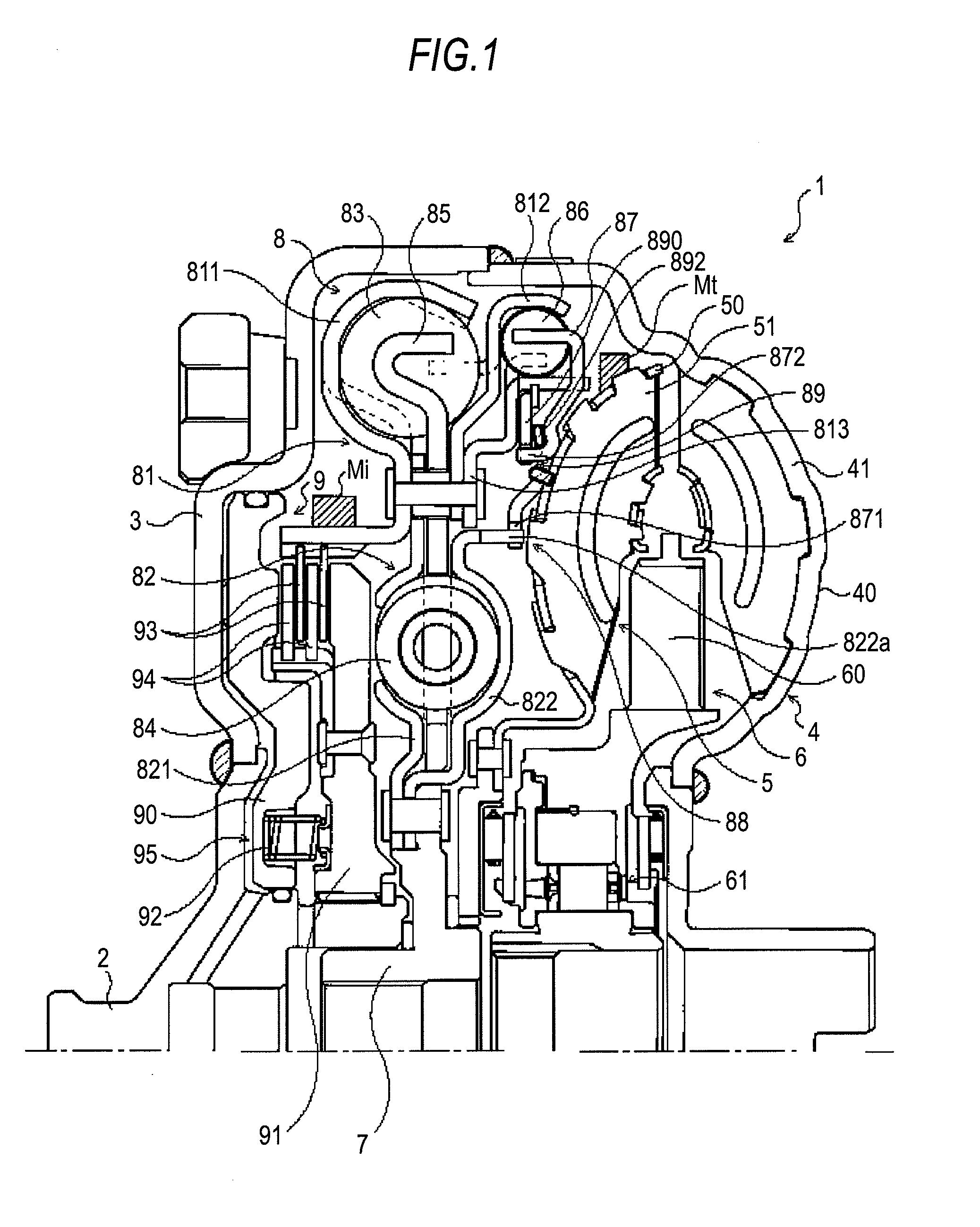
[0026]FIG. 1 is a cross-sectional view showing a hydraulic power transmission 1 according to an embodiment of the present invention. The hydraulic power transmission 1 shown in the drawing is a torque converter to be mounted on a vehicle having an engine as a prime mover as a starting device, and includes an input-side centerpiece (input member) 2 coupled to a crankshaft of an engine, not shown, a front cover 3 to be fixed to the input-side centerpiece 2, a pump impeller (input side hydraulic transmission element) 4 fixed to the front cover 3, a turbine runner (output side hydraulic transmission element) 5 rotatable coaxially with the pump impeller 4, a stator 6 configured to rectify the flow of hydraulic oil (hydraulic fluid) from the turbine runner 5 to the pump impeller 4, a damper hub (output member) 7 fixed to an input shaft of a variable speed gear as an automatic transmission...


PUM


Abstract

A hydraulic power transmission includes a pump impeller connected to an input member coupled to a prime mover, a turbine runner rotatable coaxially with the pump impeller, a damper mechanism having an input element, a resilient member engaged with the input element, an output element, and a lockup clutch capable of engaging the input member and the input element of the damper mechanism and releasing the engagement therebetween. The transmission also includes a dynamic damper configured in such a manner that oscillations transmitted to the input member when the input member and the input element of the damper mechanism are engaged by the lockup clutch are absorbed from the input element.

Description

INCORPORATION BY REFERENCE[0001]The disclosure of Japanese Patent Application No. 2010-081057 filed on Mar. 31, 2010, including the specification, drawings and abstract thereof, is incorporated herein by reference in its entirety.BACKGROUND OF THE INVENTION[0002]1. Field of the Invention[0003]The present invention relates to a hydraulic power transmission including a pump impeller connected to an input member coupled to a prime mover, a turbine runner rotatable coaxially with the pump impeller, a damper mechanism having an input element, a resilient member engaged with the input element, and an output element, and a lockup clutch configured to be capable of engaging the input member and the input element of the damper mechanism and releasing the engagement therebetween.[0004]2. Description of the Related Art[0005]In the related art, a torque converter provided with a direct connection clutch having a damper mechanism including a driving plate, an outer damper spring, an intermediate...

Claims


Application Information

Patent Timeline
Patent Type & Authority Applications(United States)
IPC IPC(8): F16H45/02F16F7/10
CPCF16H45/02F16H2045/021F16H2045/0284F16H2045/0231F16H2045/0247F16H2045/0226
Inventor TAKIKAWA, YOSHIHIRONAGAI, HIROKIITOU, KAZUHIRO
Owner AISIN AW CO LTD
Why Eureka
Try Eureka