Irreversible circuit activation switch

a technology of circuit activation switch and reverse circuit, which is applied in the direction of contact mechanism, cell components, snap-action arrangements, etc., can solve the problems of battery capacity depletion, unrealistic competition of new thin low cost batteries, and large power sources compared to today's standards, so as to prevent electrical communication and prevent electrical communication

a technology of circuit activation switch and reverse circuit, which is applied in the direction of contact mechanism, cell components, snap-action arrangements, etc., can solve the problems of battery capacity depletion, unrealistic competition of new thin low cost batteries, and large power sources compared to today's standards, so as to prevent electrical communication and prevent electrical communication

US20110241446A1Inactive Publication Date: 2011-10-06BLUE SPARK TECH

Image

  • Irreversible circuit activation switch
  • Irreversible circuit activation switch
  • Irreversible circuit activation switch

Examples


Embodiment Construction

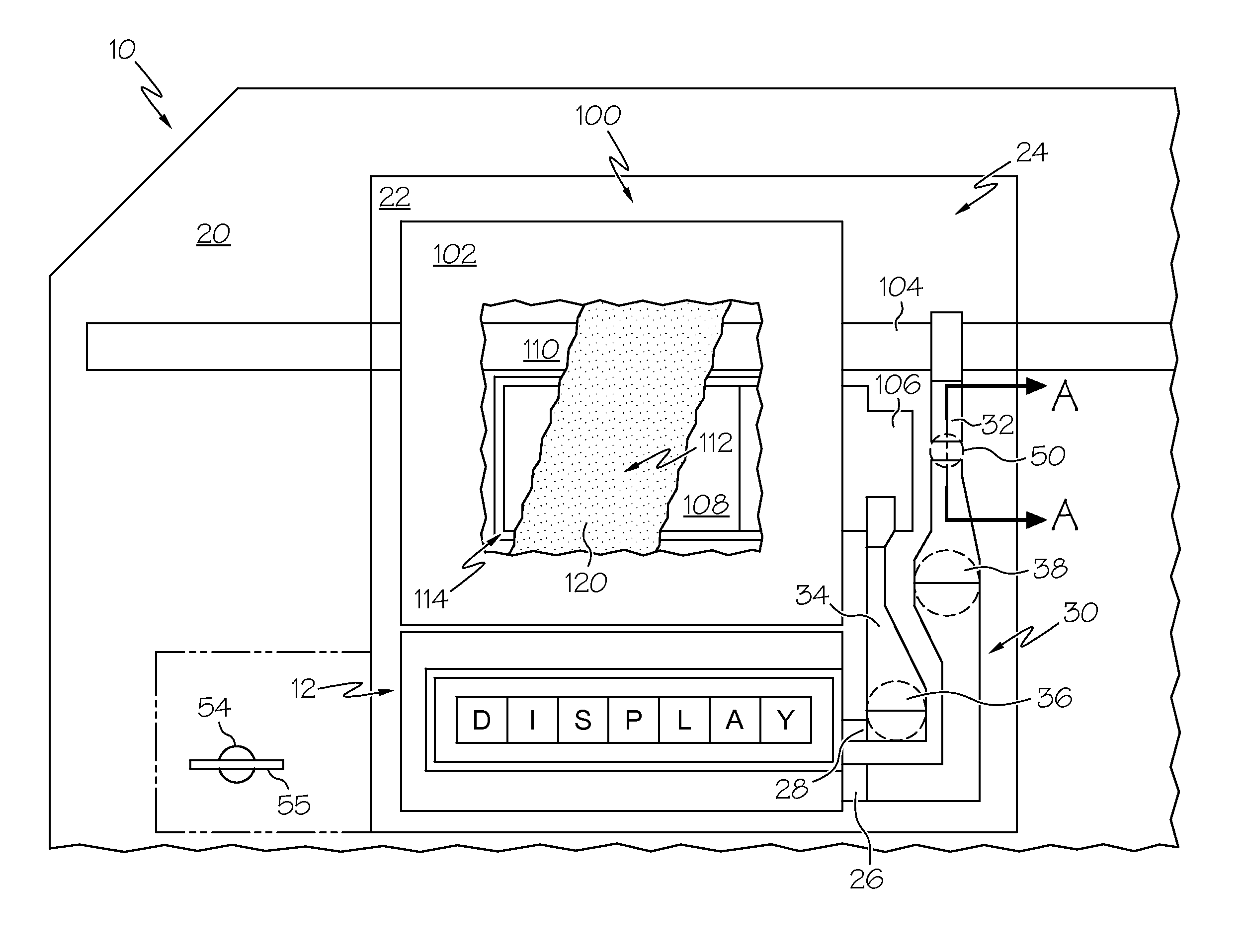
[0017]In applications where the batteries are hard wired into a circuit and there is not a switch, the current begins to flow at the time that the circuit is completed. Typically this type of circuit could include a display, IC chip, sensor, antennae (e.g., RFID antenna), and a low capacity power source such as a flat printed battery or low-profile battery. Even though the circuit may be in sleep mode, the IC chip still requires a relatively small amount of electrical current (e.g., micro amperes) to stay functional. Over time, this small current on a 24 / 7 basis consumes a large portion of the batteries capacity, thus minimizing the functional life of this circuit to the user. The time it takes for the consumer to receive this device varies from manufacturer to manufacturer depending on the manufacturing system, distribution system, and inventory levels. Even after the end user gets this electrical device, more than likely it will be not used for various periods of time, due to many...


PUM


Abstract

An electrical device is provided, including a substrate, an electrical component on the substrate, and a battery on or integrating the substrate for providing electrical energy to said electrical component. An open switch prevents electrical communication between the electrical component and the battery while open. A circuit activating component is adapted to irreversibly close the open switch to thereby establish a permanent electrical circuit between the electrical component and the battery.

Description

CROSS-REFERENCE TO RELATED APPLICATIONS[0001]This application claims the benefit of U.S. provisional application Ser. No. 61 / 318,961, filed on Mar. 20, 2010, which is incorporated herein in its entirety by reference thereto.BACKGROUND OF THE INVENTION[0002]For the past one hundred years or so, scientists have been making Carbon / Zinc portable power sources for various applications. In the early days of portable power, these power sources were very large compared to today's standards. For example, the very popular “Igniter Cell” made by Eveready was about 3″ diameter and about 9″ tall and was used in many applications such as radios, buzzers, Xmas lighting, etc. These large cells, as well as some smaller versions, such as the famous Eveready #6 (about 2″ dia.×6″ tall) and the smallest unit cell of the day, the #950 (D size), were commonly made into battery packs with voltages exceeding 40 volts in some applications. These were similar in size, and even larger, than today's car batteri...

Claims


Application Information

Patent Timeline
06 Oct 2011
Publication
US20110241446A1
IPC
H01H33/59; H01M50/528
CPC
H01H13/48; H01H5/30
Inventors
TUCHOLSKI, GARY R.