
Magnetic resonance method using a phase-modulated pulse train with a constant small flip angle

a phase-modulated pulse and magnetic resonance technology, applied in the field of magnetic resonance measurement, can solve the problems of low signal to noise ratio and limit excitation power, and achieve the effects of low excitation power, rapid sampling of data points, and low noise ratio

Inactive Publication Date: 2011-10-06
RWTH AACHEN UNIV +1
View PDF18 Cites 20 Cited by
  • Summary
  • Abstract
  • Description
  • Claims
  • Application Information

AI Technical Summary

Benefits of technology

The patent text describes a method for performing magnetic resonance measurements with a good signal to noise ratio at low excitation power. The method involves using a sequence of pulse trains with a constant power in the excitation and a constant amplitude in the Walsh transform. The pulse trains are modulated by a bent function, which ensures a constant power in the frequency domain. The method can be used for NMR, NQR, and ESR measurements. The use of the bent function allows for a homogeneous excitation of frequencies within a frequency window determined by the pulse spacing. The method also allows for a scanning of a time grid where adjacent points are separated by the time interval. The use of the bent function as a discrete representation of rotating waves allows for a more accurate description of the pulse trains. Overall, the method provides a better signal to noise ratio with low excitation power and a high response power.

Problems solved by technology

Furthermore, when performing NMR measurements with mobile NMR devices it is necessary to limit excitation power to increase battery life.
Nevertheless, in NMR techniques known from prior art the drawback of low excitation power is an insufficient response peak power which results in a low signal to noise ratio and necessitates to repeat the measurements frequently while summing up the results to increase signal to noise.
Similar problems arise in other magnetic resonance methods as electron spin resonance (ESR) and nuclear quadrupole resonance (NQR).

Method used


Image

  • Magnetic resonance method using a phase-modulated pulse train with a constant small flip angle
  • Magnetic resonance method using a phase-modulated pulse train with a constant small flip angle
  • Magnetic resonance method using a phase-modulated pulse train with a constant small flip angle

Examples


Embodiment Construction

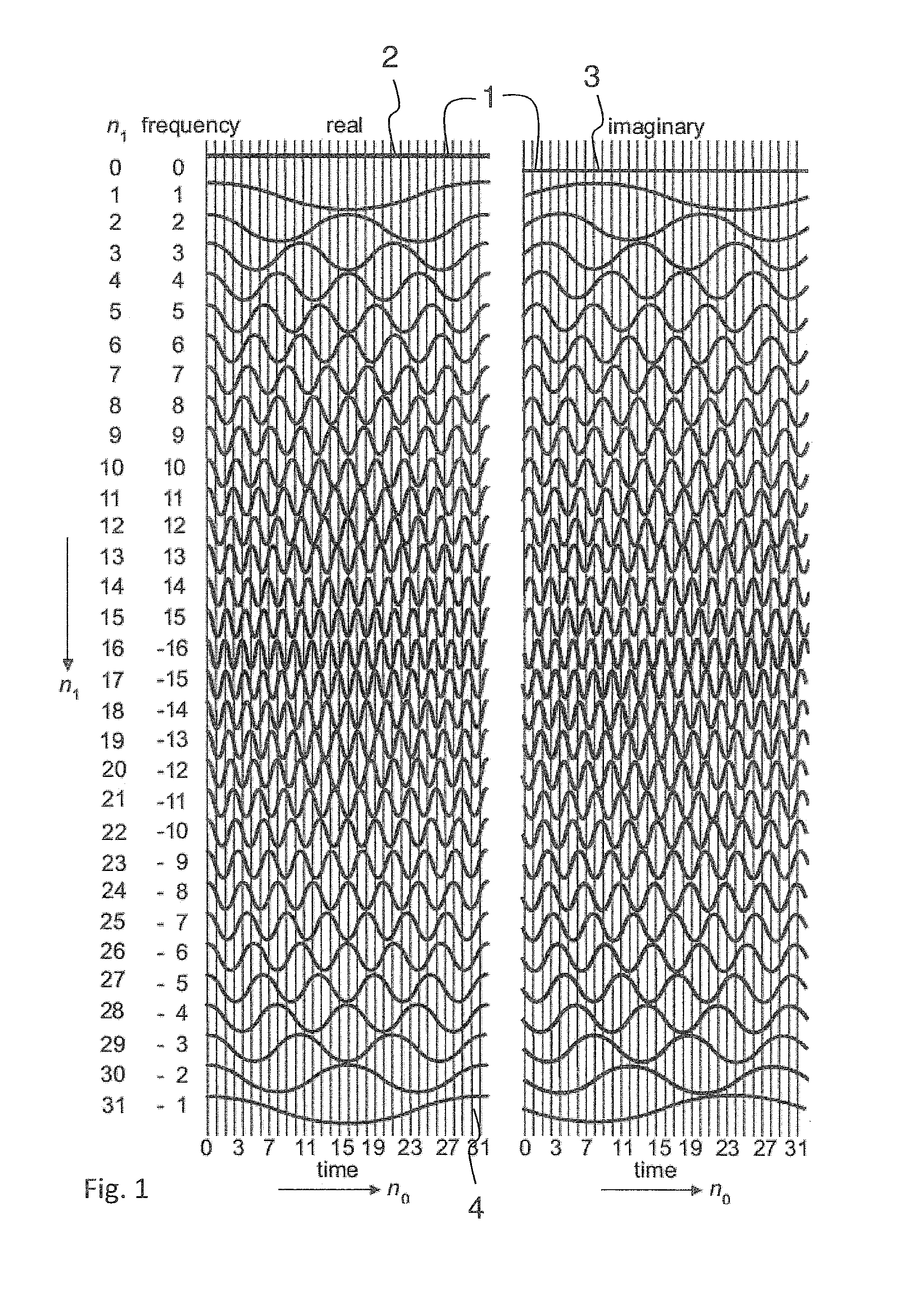
FIG. 1 depicts schematically an NMR pulse train with 1024 data points. For the sake of clarity the pulse sequence is illustrated in FIG. 1 in a two-dimensional fashion. According to the m-ary representation of n=mn1+n0 the horizontal numerals refer to n0 whereas the vertical numerals refer to n1. Both range from 0, . . . , 31, where for typesetting reasons the n0 numerals are only partly furnished.

The pulse trains 1 are shown with their respective real component 2 and the imaginary component 3 corresponding to the projections of the pulse trains 1 to the x and y directions in the rotating coordinate frame the frequency of which is defined by the so called Larmor frequency which is proportional to the static magnetic field at the sample. For sake of clarity the reference numerals are only depicted for one pulse train 1 (wavelet) with frequency n1=0 but not for the respective pulse trains 1 with n1=1 to 31 (according to equation (4) above). Therefore, both the first number of pulse tr...


PUM


Abstract

A method for performing magnetic resonance measurements on a sample includes applying a first predetermined number of pulse trains for excitation, each pulse train having a constant amplitude and including a second predetermined number of pulses spaced by a predetermined time interval. The pulse trains are modulated by a bent function. After each pulse, data is sampled. Preferably a square number of pulses is generated being constant in power, and the Walsh transform of the sequence of their phases is constant in power, so that the power of the excitation in time and frequency domain is constant. The method can reduce power requirements and may permit undercutting specific absorption rate (SAR) limits due to the small excitation power necessary to create time signals with reasonable signal to noise ratio.

Description

BACKGROUNDThe invention relates to performing magnetic resonance measurements such as spectroscopic NMR (nuclear magnetic resonance) measurements as well as in MRI (magnetic resonance imaging).In NMR experiments spins in a sample are aligned by a static magnetic field. The aligned spins are then excited by applying electromagnetic pulses to the sample. This can be done in immobile spectrometers which often comprise a superconducting magnet or with portable NMR devices which are e.g. known by the trademark NMR-Mouse in the market. In particular when imaging human beings it is important to limit the excitation power which is introduced by the electromagnetic pulses to the patient for to undercut specific absorption rate (SAR) limits. Furthermore, when performing NMR measurements with mobile NMR devices it is necessary to limit excitation power to increase battery life. Therefore, low excitation power is desirable. Nevertheless, in NMR techniques known from prior art the drawback of lo...

Claims


Application Information

Patent Timeline
Patent Type & Authority Applications(United States)
IPC IPC(8): G01V3/14G01R33/44
CPCG01N24/08G01N24/081G01N24/084G01N24/087G01R33/60G01R33/44G01R33/441G01R33/4616G01R33/561G01N24/10
Inventor BLUMICH, BERNHARDGREFERATH, MARCUSBYRNE, EIMEARGONG, QINGXIA
Owner RWTH AACHEN UNIV
Learn More