Mobility cell measurement method and apparatus for mobile communications system

a mobile communication system and mobile communication technology, applied in the field of mobile communication technologies, can solve the problems of large power consumption of user equipment, large time delay of mobility measurement, and 3gpp has not determined a mobility measurement method

Inactive Publication Date: 2011-10-06
SAMSUNG ELECTRONICS CO LTD +1
View PDF5 Cites 17 Cited by
  • Summary
  • Abstract
  • Description
  • Claims
  • Application Information

AI Technical Summary

Benefits of technology

[0012]To address the above-discussed deficiencies of the prior art, it is a primary object to provide a mobility measurement method for a mobile communications system such as an LTE-A system, so as to increase the speed of the mobility measurement and reduce the power consumption of the user equipment.
[0020]As can be seen from the above technical solutions, in the method provided by the present invention, by performing the synchronous transmission of the synchronous signal on at least two CCs that have corresponding antennae which have the same location and sending the information regarding the CC that is capable of performing the CA with the carrier of the serving cell and the joint mobility measurement information to the user equipment, the user equipment can determine the CC for performing the joint mobility measurement according to this information and can perform the joint mobility measurement on the determined CC without measuring the different-frequency carriers one by one, which improves the performance of the measurement, increases the speed of the mobility measurement and reduces the power consumption of the user equipment.

Problems solved by technology

As a quantity of the different-frequency carrier increases, the time delay of the mobility measurement is larger, and power consumption of the user equipment is larger.
However at present, the 3GPP has not determined a mobility measurement method with respect to the LTE-A system.
If the mobility measurement method in the LTE system is still used, the user equipment performs the measurement on the 6 RBs at the center of the different-frequency carrier one by one, which apparently leads to longer time and larger power consumption resulting from the mobility measurement.

Method used


Image

  • Mobility cell measurement method and apparatus for mobile communications system
  • Mobility cell measurement method and apparatus for mobile communications system
  • Mobility cell measurement method and apparatus for mobile communications system

Examples


embodiment 1

[0075]The CA uses the deployment scenario 1. That is, there are other M−1 CCs that have the same coverage range in addition to the CC k, and the M CCs correspond to the antennae having the same location and using the same PCI. Certain user equipment is located within the coverage range. Specifically, the CC k is configured as the PCC of the user equipment. That is, the cell determined from the PCC and the PCI is the serving cell of the user equipment.

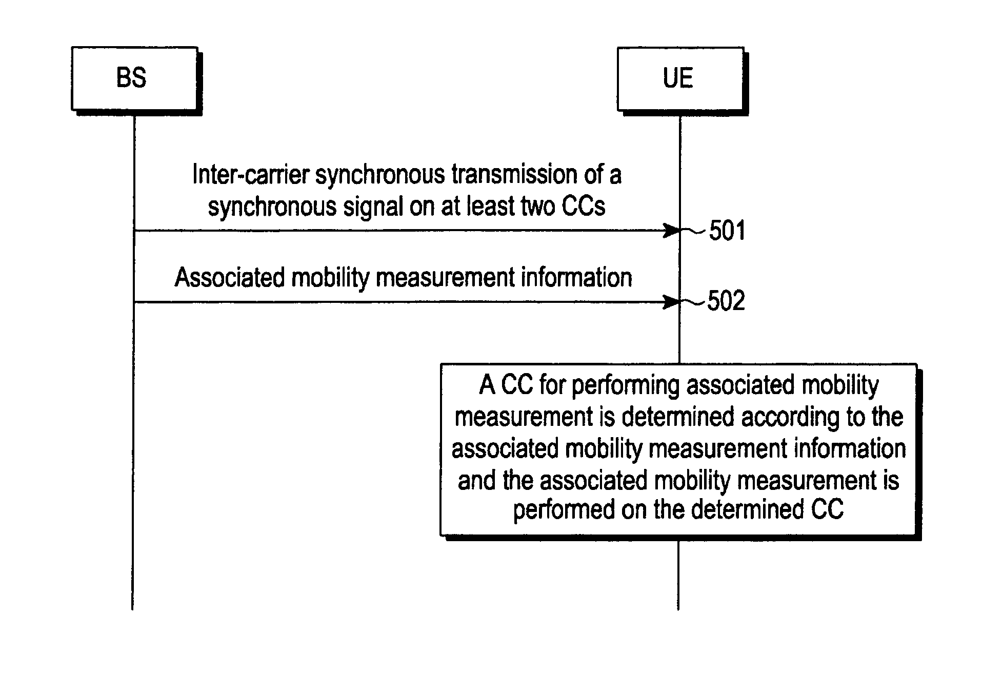
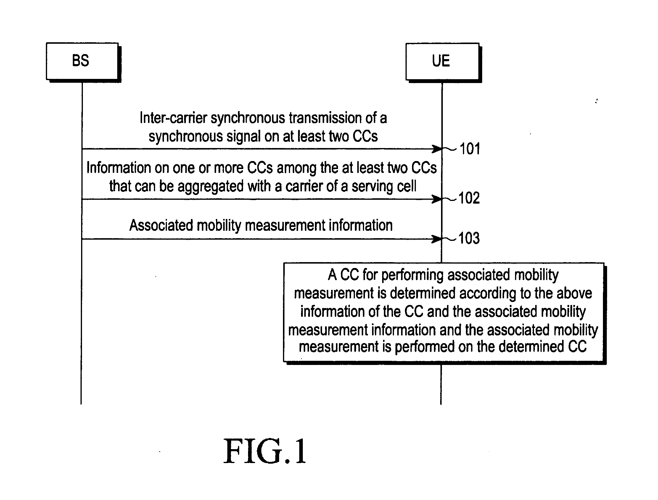
[0076]According to a method of the present invention, the following is considered.

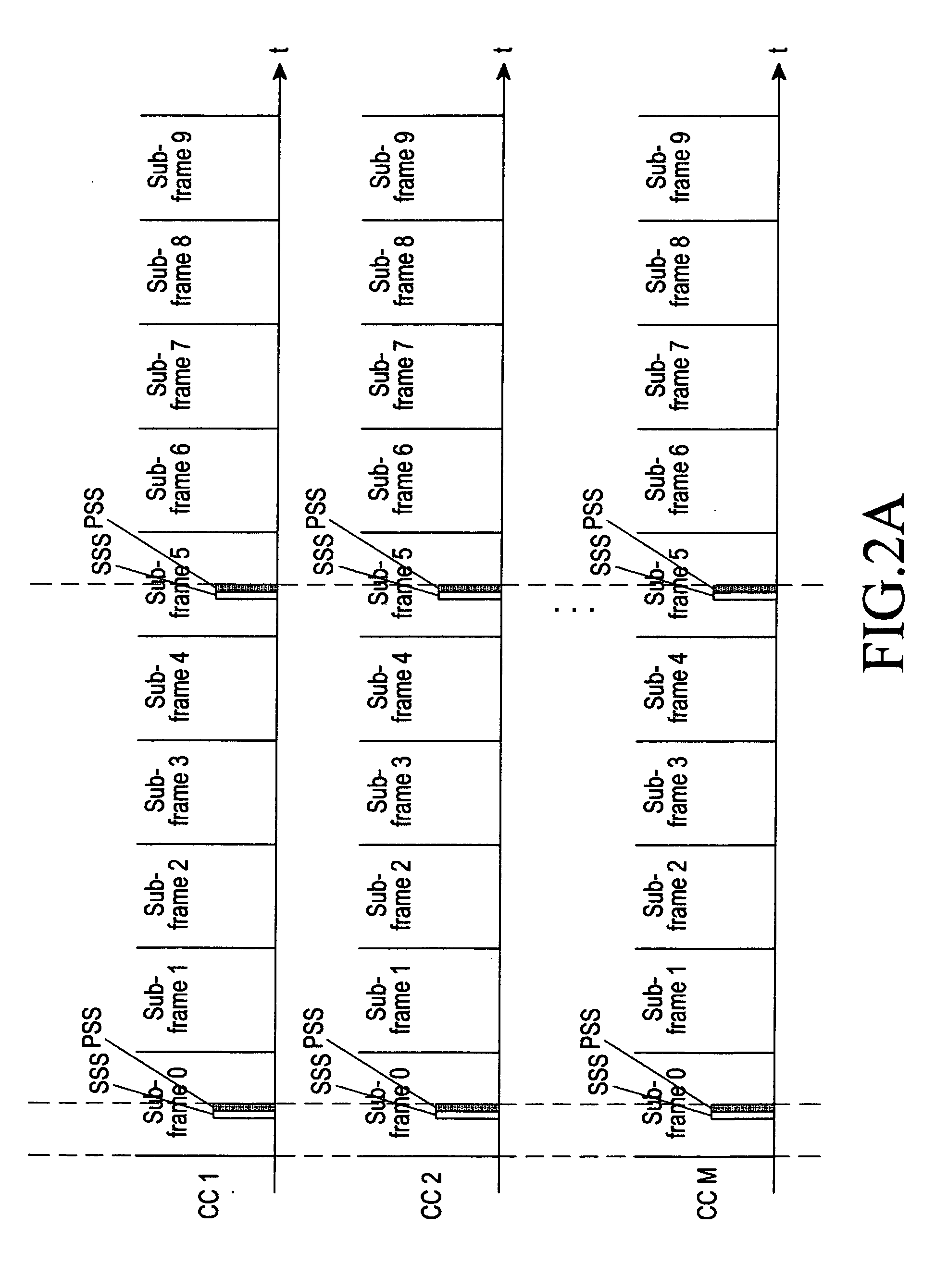
[0077]The base station to which the M CCs belongs sends the PSS and the SSS in a synchronous manner on the M CCs, and the PSS and the SSS sent on the M CCs have the same sequence.

[0078]The base station for the serving cell of the user equipment sends the information regarding the other M−1 CCs, i.e. the information regarding the CC that is capable of performing the CA with the PCC, to the UE. Specifically, the base station can select N CCs from the M−1 CCs...

embodiment 2

[0089]The CA uses the deployment scenario 2. That is, there are other M−1 CCs in addition to the CC k. The M CCs correspond to the antennae having the same location and the same direction, and use the same PCI. However, the cell covered by the M CCs has distinct coverage ranges. Certain user equipment is located within the coverage range of the cell of the CC k. Specifically, the CC k is configured as the PCC of the user equipment. That is, the cell determined from the PCC and the PCI is the serving cell of the user equipment.

[0090]Several examples of combining the above joint mobility measurement information are listed in the following. For example, the second and the seventh manners are combined. That is, the information for indicating the manner that the user equipment performs the joint mobility measurement and the information for indicating the CC required for performing the joint mobility measurement are merged. Thus, after receiving the above information, the user equipment d...

embodiment 3

[0104]The CA uses the deployment scenario 1 or 2. There are other M−1 CCs in addition to the CC k. They may have the same coverage range or distinct coverage ranges. The M CCs correspond to the antennae having the same location and the same direction, but use distinct PCIs. Certain user equipment is located within the coverage range. Specifically, the CC k is configured as the PCC of the user equipment.

[0105]According to a method of the present invention, the following is considered.

[0106]The base station to which the M CCs belongs sends the PSS and the SSS in a synchronous manner on the M CCs, and the PSS and the SSS sent on the M CCs have the same sequence.

[0107]The base station for the serving cell of the user equipment sends the information regarding the other M−1 CCs, i.e. the information regarding the CC that is capable of performing the CA with the PCC, to the UE. Specifically, the base station can select N CCs from the M−1 CCs according to channel conditions on each CC or se...


PUM


Abstract

This invention provides a mobility cell measurement method and apparatus for a mobile communications system like as LTE-A. The method includes: performing inter-carrier synchronous transmission of a synchronous signal on at least two Component Carriers (CCs); sending information regarding one or more CCs among the at least two CCs that is capable of performing Carrier Aggregation (CA) with a carrier of a serving cell to a user equipment through higher-level signaling; and sending joint mobility measurement information to the user equipment of the serving cell, wherein the user equipment determines a CC for performing joint mobility measurement according to the information regarding the one or more CCs and the joint mobility measurement information and performs the joint mobility measurement on the determined CC. This increases the speed of the mobility measurement and reduces the power consumption of the user equipment.

Description

CROSS-REFERENCE TO RELATED APPLICATION(S) AND CLAIM OF PRIORITY[0001]The present application claims the benefit under 35 U.S.C. §119(a) to a Chinese patent application filed in the Chinese Intellectual Property Office on Apr. 2, 2010 and assigned Serial No. 201010144619.1, the entire disclosure of which is hereby incorporated by reference.TECHNICAL FIELD OF THE INVENTION[0002]The present invention relates to the field of mobile communication technologies and, more particularly, to a mobility cell measurement method and apparatus for a mobile communications system.BACKGROUND OF THE INVENTION[0003]In an existing Long Term Evolution (LTE) system, various system bandwidths, 1.4 MHz, 3 MHz, 5 MHz, 10 MHz, 15 MHz and 20 MHz, can be supported. Regardless of the system bandwidth, a Primary Synchronization Signal (PSS) and a Secondary Synchronization Signal (SSS) used for mobility measurement are both transmitted on a bandwidth of 6 Resource Blocks (RBs) at a center of the entire system band...

Claims


Application Information

Patent Timeline
Patent Type & Authority Applications(United States)
IPC IPC(8): H04W24/00
CPCH04L5/001Y02B60/50H04W56/00H04W24/10Y02D30/70
Inventor SUN, CHENGJUN
Owner SAMSUNG ELECTRONICS CO LTD
Why Eureka
Try Eureka