Control system

a control system and control system technology, applied in the direction of machines/engines, engine starters, transportation and packaging, etc., can solve the problems of increasing the engagement pressure of the clutch, reducing the rotational speed of the rotary electric machine, and not being able to start the internal combustion engine, etc., to suppress the rise in the acceleration rate of the rotational speed, increasing the rotational speed, and reducing the input member's rotational speed

Active Publication Date: 2011-10-06
AISIN AW CO LTD
View PDF4 Cites 33 Cited by
  • Summary
  • Abstract
  • Description
  • Claims
  • Application Information

AI Technical Summary

Benefits of technology

[0022]According to this configuration, the starting rotational speed can be set to a rotational speed that is as near as possible to the reference rotational speed within a range capable of preventing torque transmission from the input member to the output member. Thus, time spans for decreasing the rotational speed of the input member from the reference rotational speed to the starting rotational speed and for conversely increasing the rotational speed of t

Problems solved by technology

However, if the added torque is smaller than the actual cranking torque, the increase in the engagement pressure of the clutch is accompanied by a drop in the rotational speed of the rotary electric machine, and it may not be possible to start the internal combustion engine.
Conversely, if the added torque is larger than the actual cranking torque, a torque that is larger than the driving force requested by the driver and more than is needed for starting the internal co

Method used


Image

  • Control system
  • Control system
  • Control system

Examples


first embodiment

1. First Embodiment

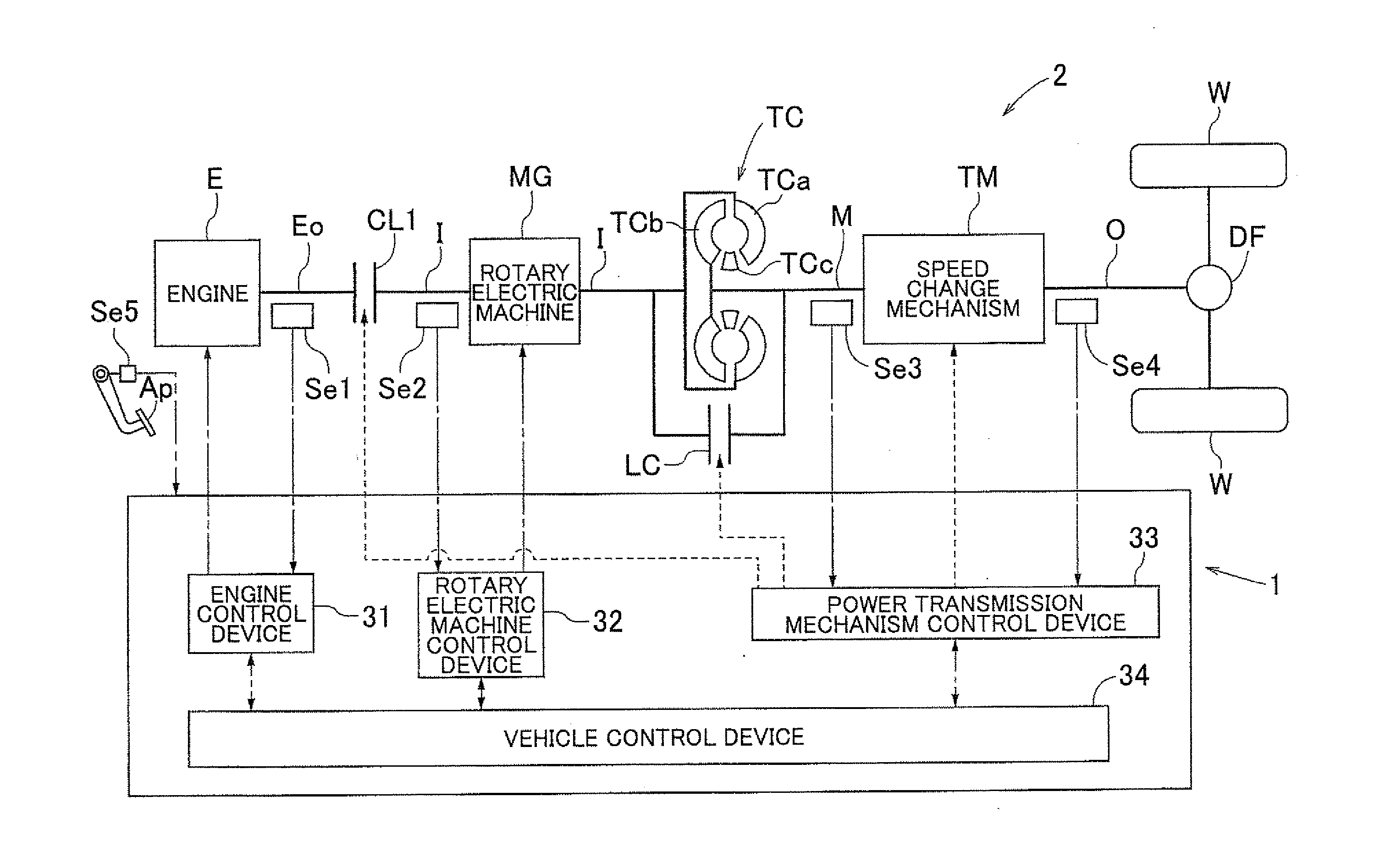
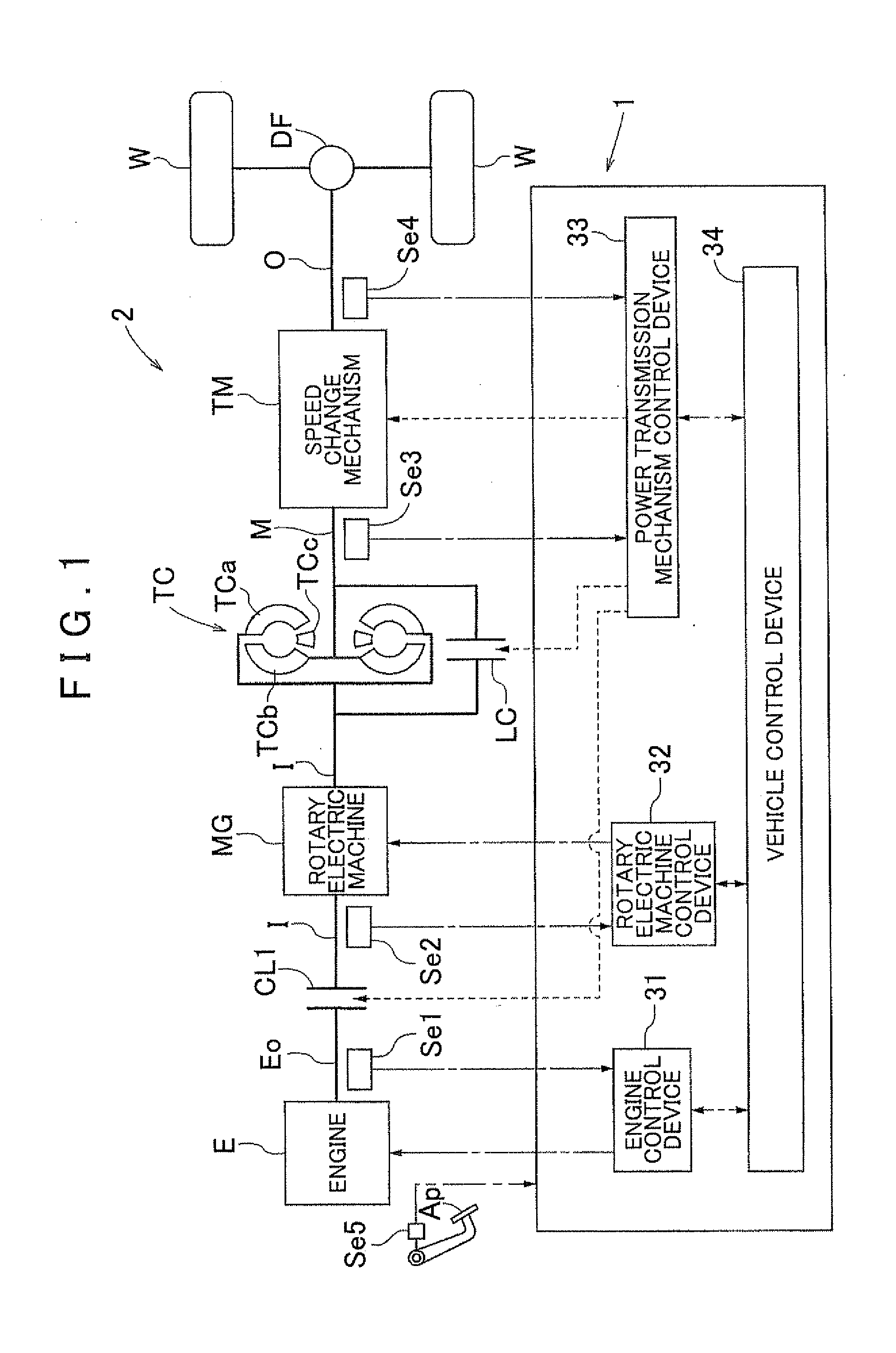
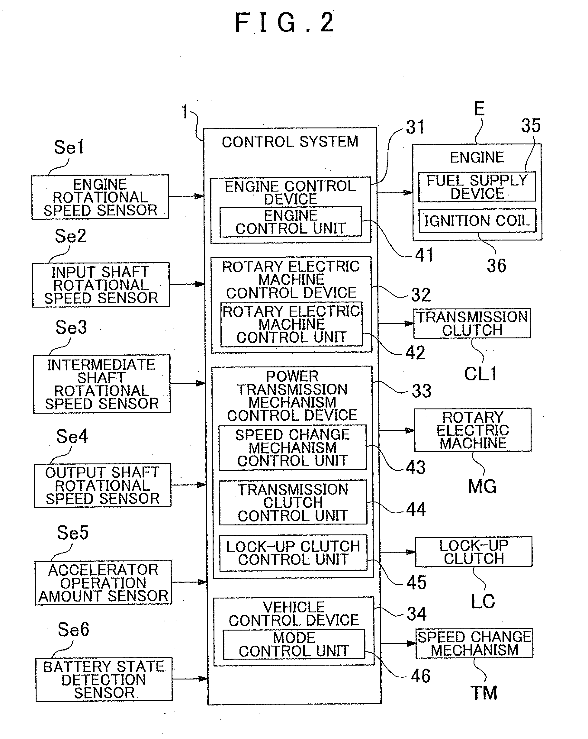
[0034]A first embodiment of a control system 1 according to the present invention will be described with reference to the drawings. The control system 1 performs a control of a hybrid vehicle drive system 2 that includes an input shaft I, a transmission clutch CL1, an output shaft O, and a speed change mechanism TM. The input shaft I serves as an input member that is drivingly connected to a rotary electric machine MG. The transmission clutch CL1 selectively and drivingly connects the input shaft I to an engine E that is an internal combustion engine. The output shaft O serves as an output member that is drivingly connected to a wheel W. The speed change mechanism TM includes a plurality of engagement elements, and has a plurality of shift speeds selectively formed by controlling the engagement and disengagement of the plurality of engagement elements. A rotational speed of the input shaft I is changed by a speed ratio of the respective shift speeds and transmitte...

second embodiment

4. Second Embodiment

[0123]A second embodiment of the control system 1 according to the present invention will be described with reference to the drawings. FIGS. 9 and 10 are drawings that show a control of the mode control unit 46 according to the present embodiment. The mode control unit 46 according to the present embodiment differs from the first embodiment with respect to the content of the start control that starts combustion in the engine E by increasing the engagement pressure of the transmission clutch CL1. Otherwise, the constitution of the second embodiment is basically identical to that of the first embodiment. The following description will focus on points where the start control according to the present embodiment differs from that of the first embodiment. Note that aspects not described in particular detail are similar to those of the first embodiment.

4-1. Increase in Rotational Speed of Engine

[0124]During execution of the rotational speed feedback control, the mode co...


PUM


Abstract

A control system configured with a speed change mechanism. When starting combustion in an internal combustion engine under a combustion-stopped vehicle running condition, the combustion in the internal combustion engine is stopped, the speed change mechanism forms the one-way transmission speed, and the output member rotates. A rotational speed feedback control is executed that sets a value that multiplies a rotational speed of the output member by a speed ratio of the one-way transmission speed as a reference rotational speed of the input member, sets a starting rotational speed, and controls a rotary electric machine such that the rotational speed of the input member matches the target rotational speed. During execution of the rotational speed feedback control, a start control is performed that increases engagement pressure of the clutch to increase a rotational speed of the internal combustion engine and start combustion in the internal combustion engine.

Description

INCORPORATION BY REFERENCE[0001]The disclosure of Japanese Patent Application No. 2010-080561 filed on Mar. 31, 2010 including the specification, drawings and abstract is incorporated herein by reference in its entirety.BACKGROUND OF THE INVENTION[0002]The present invention relates to a control system that performs a control of a hybrid vehicle drive system that includes: an input member that is drivingly connected to a rotary electric machine; a clutch that selectively and drivingly connects the input member to an internal combustion engine; an output member that is drivingly connected to a wheel; and a speed change mechanism that has a plurality of shift speeds selectively formed by controlling the engagement and disengagement of a plurality of engagement elements, and changes a rotational speed of the input member by a speed ratio of the respective shift speeds and transmits the changed rotational speed to the output member.DESCRIPTION OF THE RELATED ART[0003]Hybrid vehicles that...

Claims


Application Information

Patent Timeline
IPC IPC(8): B60W10/06B60W10/02B60W30/18B60K6/383B60K6/48B60K6/547B60W10/08B60W20/00F02D29/00F02D29/02F02N11/04F16H59/74F16H61/02F16H63/40F16H63/50
CPCB60K6/48B60W10/02B60W30/192F02D17/04F02D29/02F16H61/686Y10T477/78Y02T10/6221F16H2312/14F16H2059/186Y10T477/26Y10T477/32F16H2200/2023Y02T10/62
Inventor YOSHIDA, TAKASHIHAKUMURA, YOMEIIZAWA, JINTAJIMA, YOICHI
Owner AISIN AW CO LTD
Why Eureka
Try Eureka