
Truck trailer refrigeration system

a refrigeration system and trailer technology, applied in the field of truck trailer transportation refrigeration systems, can solve the problems of significant design space limitations, and achieve the effect of optimizing the operation

Active Publication Date: 2011-10-13
CARRIER CORP
View PDF6 Cites 42 Cited by
  • Summary
  • Abstract
  • Description
  • Claims
  • Application Information

AI Technical Summary

Benefits of technology

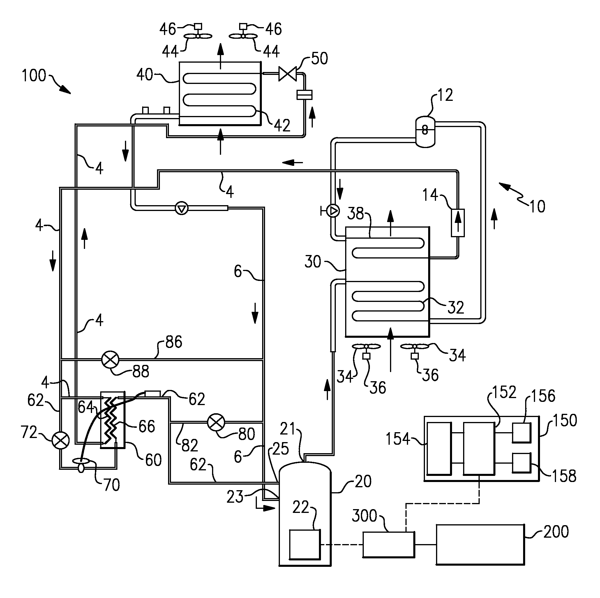
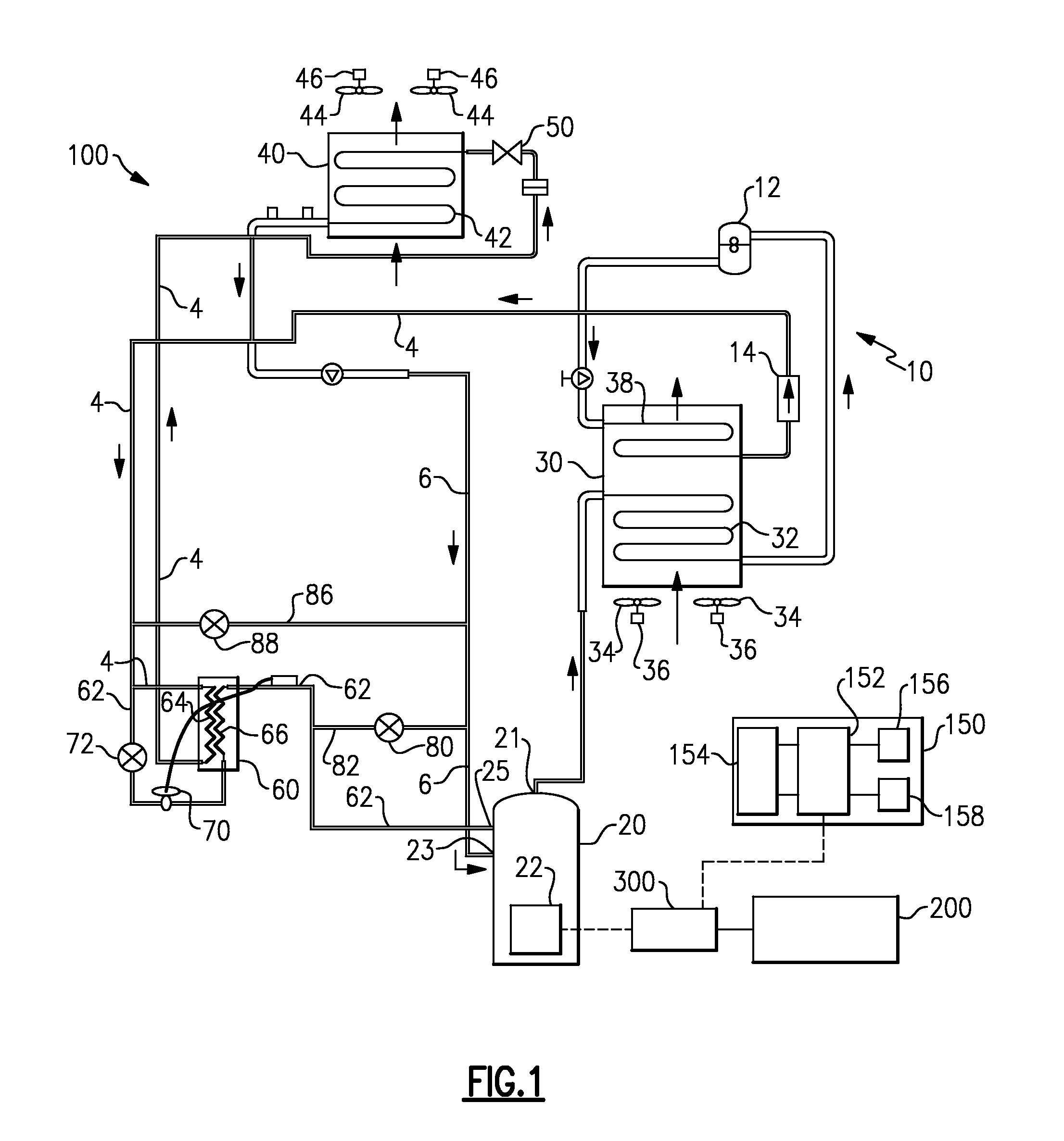
[0007]In an aspect of the invention, an electrically powered trailer refrigeration system includes an economized scroll compressor, a condenser heat exchanger unit, an evaporator expansion device, and an evaporator heat exchange unit, arranged in a primary refrigerant circuit, an engine driven electric generator, and an economizer circuit. The economized scroll compressor has a discharge port, a suction port, an intermediate pressure stage injection port, and an electric drive motor. The condenser heat exchanger unit has a refrigerant inlet coupled in refrigerant flow communication with the discharge port of the compressor, a refrigerant outlet, and a condenser fan assembly having at least one electric fan motor. The evaporator heat exchanger unit has a refrigerant outlet coupled in refrigerant flow communication with the suction port of the compressor, a refrigerant inlet coupled in refrigerant flow communication with the refrigerant outlet of the condenser heat exchanger, thereby forming a primary refrigerant circuit, and an evaporator fan assembly having at least one electric fan motor. The evaporator expansion device is disposed in the primary refrigerant circuit in operative association with the evaporator. The engine driven electric generator produces A.C. electric current to power the compressor drive motor, the condenser fan motor and the evaporator fan motor. The economizer circuit is operatively associated with the economized scroll compressor and in refrigerant flow communication with the intermediate compression stage injection port of the economized scroll compressor. The refrigeration system may also include a controller for selectively operating the economized scroll compressor in one of an economized mode or a non-economized mode during high refrigeration capacity demand on the refrigeration system
[0008]In an embodiment, the electrically powered trailer refrigeration system may include a bypass circuit operatively associated with the primary refrigerant circuit and the economizer circuit and also a controller for selectively operating the economized scroll compressor in one of a non-economized mode or a bypass mode during low refrigeration capacity demand on the refrigeration system.
[0009]In an aspect of the invention, a method is provided for optimizing the operation of an electrically powered trailer refrigeration system including a refrigeration unit including a refrigeration compressor driven by an electric motor, a condenser heat exchanger unit having at least one condenser fan driven by an electric motor, and an evaporator heat exchanger unit having at least one evaporator fan driven by an electric motor, the refrigeration compressor, the condenser heat exchanger unit and the evaporator heat exchanger unit coupled in refrigerant flow communication in a primary refrigerant circuit, and an electric generator for providing power to each of the compressor drive motor, the condenser fan motor and the evaporator fan motor. The method includes the steps of: providing a scroll compressor selectively operable in an economized mode or a non-economized mode as the refrigeration compressor; providing an economizer circuit in operative association with the scroll compressor, the economizer circuit being selectively opened or closed; determining a maximum power available from the electric ge

Problems solved by technology

Although electrically powered trailer refrigeration units have exhibited improved reliability, due in part to the reciprocating compressor being motor driven as opposed to belt driven, the electrical losses due to the all electric architecture of current electrically powered trailer refrigeration units present challenges when designing a system to meet refrigeration capacity targets.
This results in significant design space limitations.

Method used


Image

  • Truck trailer refrigeration system
  • Truck trailer refrigeration system

Examples


Embodiment Construction

[0013]Referring now to FIG. 1, there is shown schematically, an exemplary embodiment of a truck trailer refrigeration system 100 including a prime mover 200, a electric generator 300 operatively associated with the prime mover 200, and a transport refrigeration unit 10. The transport refrigeration unit 10 functions to regulate and maintain a desired product storage temperature range within a refrigerated volume wherein a perishable product is stored during transport, such as a refrigerated box of a trailer. The refrigeration unit 10 includes a compressor 20, a condenser heat exchanger unit 30 including a condenser heat exchange coil 32 and at least one associated condenser fan 34 and fan motor 36 assembly, an evaporator heat exchanger unit 40 including an evaporator heat exchanger coil 42 and at least one associated evaporator fan 44 and fan motor 46 assembly, and an evaporator expansion device 50, such as an electronic expansion valve (EXV) or a thermostatic expansion valve (TXV), ...


PUM


Abstract

The refrigeration unit of an electrically powered trailer refrigeration system includes an economized scroll compressor and an economizer circuit selectively operable to inject refrigeration vapor into an intermediate stage of the scroll compressor. An engine driven generator produces AC current to power the scroll compressor and other electric components of the system. During operation of the refrigeration system at high capacity demand, a controller will operate the refrigeration system in an economized mode if sufficient electric power is available from the generator and in the non-economized mode if insufficient power is available to sustain operation of the refrigeration system in the economized mode.

Description

CROSS-REFERENCE TO RELATED APPLICATION[0001]Reference is made to and this application claims priority from and the benefit of U.S. Provisional Application Ser. No.: 61 / 141,074, filed Dec. 29, 2008, and entitled TRUCK TRAILER REFRIGERATION SYSTEM.FIELD OF THE INVENTION[0002]This invention relates generally to truck trailer transport refrigeration systems and, more particularly, to reducing engine horsepower and generator power required to operate an electrically powered truck trailer refrigeration unit.BACKGROUND OF THE INVENTION[0003]Truck trailers used to transport perishable and frozen goods include a refrigerated trailer pulled behind a track cab unit. The refrigerated trailer, which houses the perishable or frozen cargo, requires a refrigeration unit for maintaining a desired temperature environment within the interior volume of the container. The refrigeration unit must have sufficient refrigeration capacity to maintain the product stored within the trailer at the desired tempe...

Claims


Application Information

Patent Timeline
IPC IPC(8): F25B1/00F25B27/00
CPCB60Y2200/147F25B27/00F25B1/10F25B2600/2501F25D11/003F25B2400/13
Inventor AWWAD, NADER S.STOCKBRIDGE, MICHAEL
Owner CARRIER CORP
Learn More