Thermoforming apparatus

Inactive Publication Date: 2011-10-13
SAAB AB
View PDF3 Cites 0 Cited by
  • Summary
  • Abstract
  • Description
  • Claims
  • Application Information

AI Technical Summary

Benefits of technology

[0016]Thereby the same temperature can be achieved for both the first chamber and the second chamber which is beneficial for the heat distribution to the blank. In th

Problems solved by technology

Today the use of an air circulation means is common in ovens or in autocl

Method used


Image

  • Thermoforming apparatus
  • Thermoforming apparatus
  • Thermoforming apparatus

Examples


first embodiment

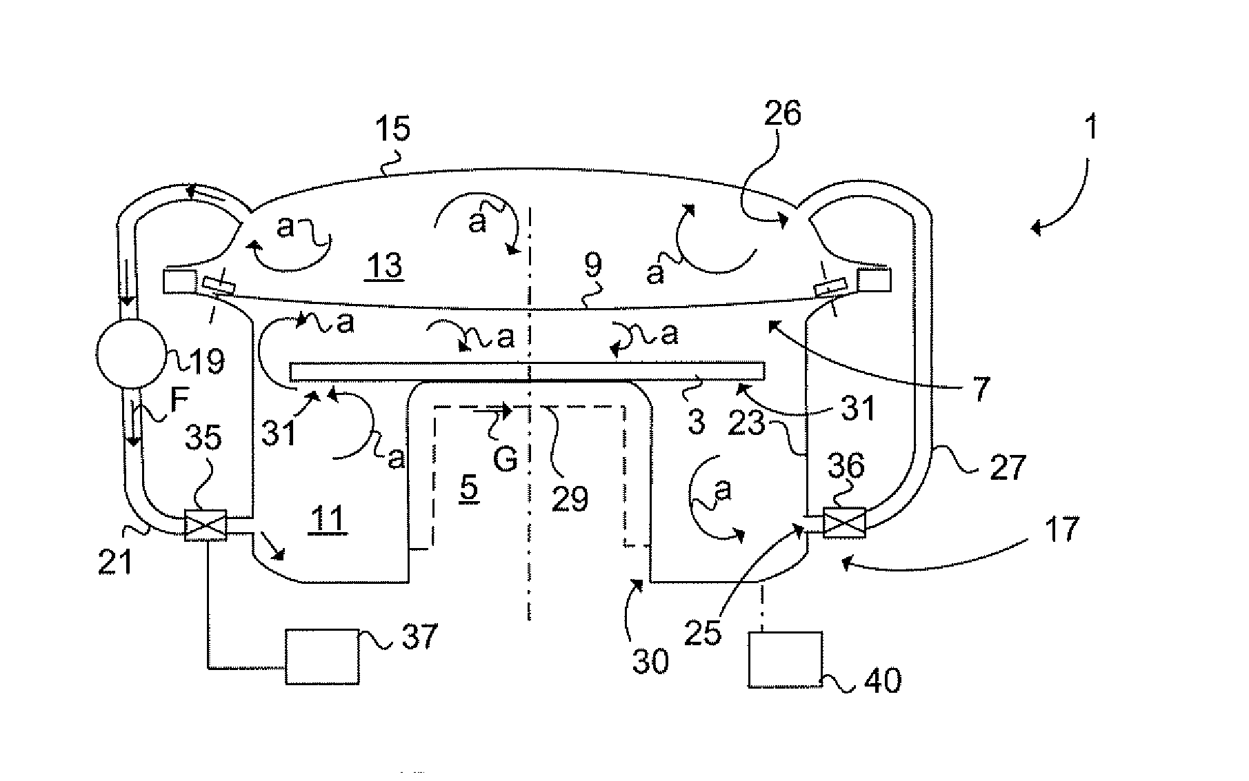
[0035]FIG. 1a schematically illustrates a thermoforming apparatus 1 according to a The thermoforming apparatus 1 is arranged for forming a blank 3 into a composite article and comprises an elongated forming tool 5 for forming the composite article (such as a beam), a forming member 7 for forming the blank 3 over the forming tool 5. The forming member 7, here an elastic vacuum bag 9, separates a first chamber 11, arranged for containing the blank 3, from a second chamber 13. The volumes of the first 11 and second 13 chamber are variable depending on the state of forming the blank 3 onto the forming tool 5 and the location of the forming member 7. The blank 3 is applied onto the forming tool 5 and being enclosed by the vacuum bag 9. The thermoforming apparatus 1 comprises a cover 15 which is removable fastened air tight to a forming tool fundament 17. An air pump 19 is arranged to an isolated first air pipe 21, which is connecting the second chamber 13 with the first chamber 11. The ...

second embodiment

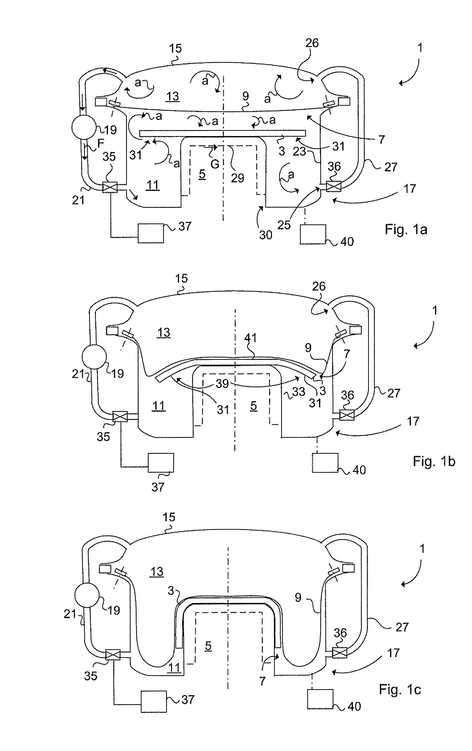
[0039]FIG. 2 illustrates schematically a thermoforming apparatus 1 having an additional heating device 43 connected to the first air pipe 21. By means of the control unit 37, the heating device 43, here a heating conductor, is controlled to produce a uniform heat to the circulated air a by heating the air flow in the first air pipe 21. The blank 3 is a rather thick lay-up of prepreg material, the thickness of which is 10-80 mm. preferably 35-55 mm.

[0040]A fan 45 is installed in the first air pipe 21 for producing the circulation of air in the first 11 and second 13 chamber. The blank 3 will have a uniform raised temperature in the initial state of forming by means of the circulated heated air in the fist chamber 11, which comprises the forming tool 5 supporting the blank 3. The first 21 and second 27 air pipes constitute in co-operation with the fan 45, a first air circulation means as well as a second air circulation means for the first 11 respective second 13 chamber. The first a...


PUM


Abstract

A thermoforming apparatus for forming a blank into a composite article. The thermoforming apparatus includes a forming tool. A forming member forms the blank over the forming tool. A first chamber is arranged for containing the blank. A second chamber is separated from the first chamber by the forming member. A first air circulator is configured to circulate air in the first chamber for achieving a heat distribution to the blank. The first air circulator includes a controllable valve member. The apparatus also includes a second air circulator. A method for forming a blank during circulation of air in a first chamber.

Description

TECHNICAL FIELD[0001]The present invention relates to a thermoforming apparatus according to the pre-characterising part of claim 1 and to a method according to claim 7.[0002]The article to be formed can be made of a thermo setting plastic, such as resin composite, epoxy resins or of a thermoplastic, polyester resin, fibreglass or carbon fibre reinforced plastic etc.[0003]The present invention relates generally to aircraft industry, but is not limited to that.BACKGROUND ART[0004]The production of composite articles requires the use of pressure onto the blank for forming the blank over the forming tool. The forming member, such as a vacuum bag, is used to achieve said pressure such that wrinkles and trapped air in the blank can be forced out under vacuum pressure. The blank can be made by a so called “prepreg” material (layers or plies of fibre material previously impregnated with resin, such as thermosetting resin). The thermoforming apparatus comprising the forming member can be us...

Claims


Application Information

Patent Timeline
IPC IPC(8): B29C51/10
CPCB29C51/424B29C51/28
Inventor PETERSSON, MIKAELHALLANDER, PERANDERSSON, JANWESTERDAHL, ANDERS
Owner SAAB AB
Why Eureka
Try Eureka