Optimal inductor

a technology of inductor and inductor core, which is applied in the direction of magnets, magnetic bodies, cores/yokes, etc., can solve the problems of high energy loss, hot spot which can be difficult to cool, and harmful harmonic distortion of power electronics, so as to reduce the demand for small mechanical tolerances, reduce stray fields, and increase the magnetic flow

Active Publication Date: 2015-08-13
COMSYS
View PDF21 Cites 1 Cited by
  • Summary
  • Abstract
  • Description
  • Claims
  • Application Information

AI Technical Summary

Benefits of technology

[0026]The coil may further be offset from said optimal position to provide a higher magnetic flow towards the centre of the inductor from the coil than towards the periphery of the inductor. This reduces stray fields generated by the inductor and also reduces the demand for small mechanical tolerances during manufacturing of the inductor. The core may further comprise surface increasing structures modifying the substantially toroidal shape to increase the surface area. The surface increasing structures may be fins or ripples on the surface of the core making the core outer surface into a heat sink. A further aspect of the present invention is a method of producing a coil according to the above described coil is presented, comprising the steps of applying the insulating layer to the wire, winding the wire around the centre axis (C), compressing the winding to a ring torus shape having a circular cross section using compression means, insulating the total coil externally with electrical insulation paper and impregnating the total coil with electrical insulation resin. Compressing the wire will conform the wire thereby filling voids in the winding, increasing the performance of the inductor. The compression may further lead to plastic deformation of the conducting material. The conforming of the wire together with the plastic deformation makes it possible to shape the coil into preferred form and gain desired heat conduction. The winding is preferably compressed using an isostatic pressure of more than 65 MPa to substantially remove voids in the coil and gain the desired shape.
[0027]A current may further be applied to the wire during said compression. The heat resulting from the current flowing through the coil will cure the half-baked resin layers on the wire insulation enabling a maintained optimal coil shape after the compression stage. The half-baked resin also acts to enhance the electrical insulation properties of the electrical insulation paper that may be placed on each wire.
[0028]A further aspect of this invention is a method of producing a magnetic core where current is run through the coil, before and / or during the moulding and / or hardening phase of the material, magnetically aligning the core particles with the H-field of the coil. This alignment further enhances the performance of the inductor, increasing the permeability and reducing losses.
[0029]The inductor manufactured with an essentially torus shaped coil within a mouldable SM2C (Soft Magnetic Mouldable Composite) has many advantages.
[0030]With a mouldable soft magnetic core, the geometric properties can be optimal with respect to the soft magnetic core permeability. The greatest technical benefit of this design is that it leads to a near theoretically optimal flux path for the electromagnetic field in the inductor avoiding unnecessary corners or angles which create hotspots reducing the life time of the insulation material and create losses in the inductor. It is further a compact and homogenous design with great heat distribution and dissipation properties. The torus shape of the coil also leads to the highest degree of induction for a given core material properties as corners or angles lead to localized saturation. The high degree of compactness of the torus shaped coil, as described above, further increases the H-field considerably enabling for a considerably smaller inductor reducing materials needed resulting in a smaller, lighter, more cost effective units with great heat conductivity.
[0031]The use of the SM2C core material is a crucial part of the invention. It allows in a simple production step to form / create the optimal torus shape of the core avoiding unnecessary material outside the flux path. The direct thermal coupling between the coil and the core material achieved by moulding the material directly on the surface of the insulated coil enables the heat losses generated in the winding to easily be distributed to the outer surface of the inductor where they can be cooled away. In the moulding step it is furthermore simple to create cooling fins or ripples to further increase the cooling properties of the inductor when needed.

Problems solved by technology

An especially problematic area has been in applications where the inductor must handle at the same time a fundamental frequency of e.g. 50 Hz while at the same time filter away from the final signal higher frequencies generated by i.e. switch mode power supplies.
Similarly, power electronics often give source to harmful harmonic distortions which have become one of the greatest concerns for the power quality industry today.
This gives source to magnetic leak flow, energy losses and heating of the surrounding metal.
If the coil is wound over the air gaps there will often be considerable fringing losses, resulting in a hot-spot which can be hard to cool.
This inevitably leads to limitations in design freedom resulting in ineffective and un-optimized inductor designs.
In addition, many problems are still present with inductors depending on the material choices in terms of energy losses, heat and hot-spot problems, annoying sound, caused by high currents at audible frequencies, unnecessary and ineffective material usage, lower efficiency at higher frequencies, and saturation at low flux intensity, etc.
High performing inductors are also relatively expensive.

Method used


Image

  • Optimal inductor
  • Optimal inductor
  • Optimal inductor

Examples


Embodiment Construction

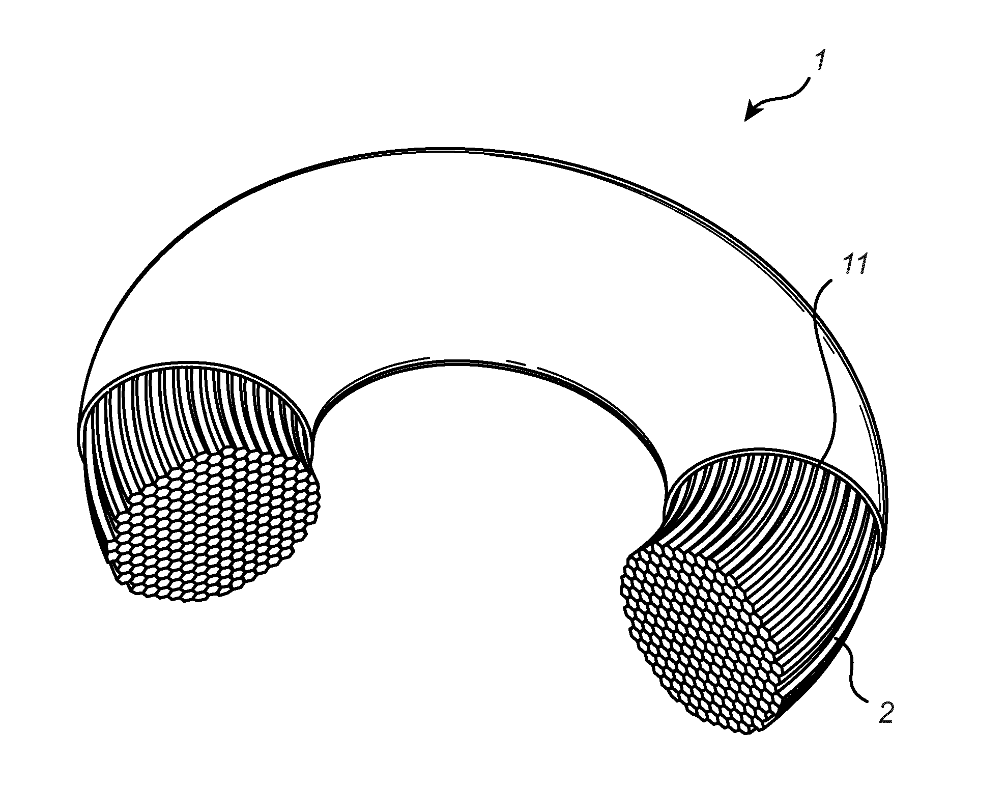
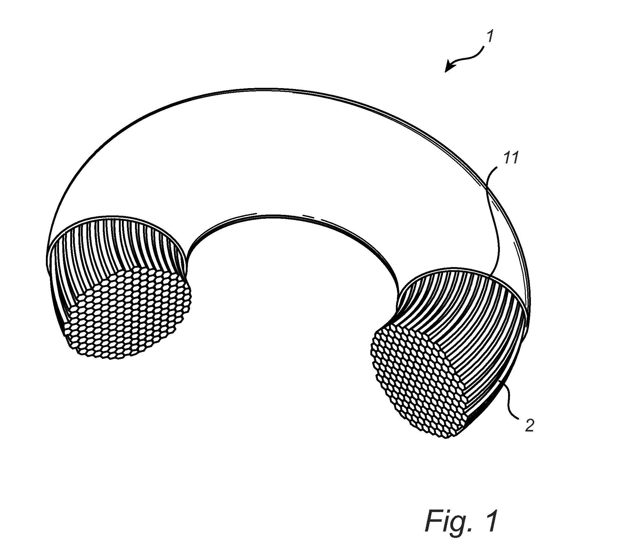
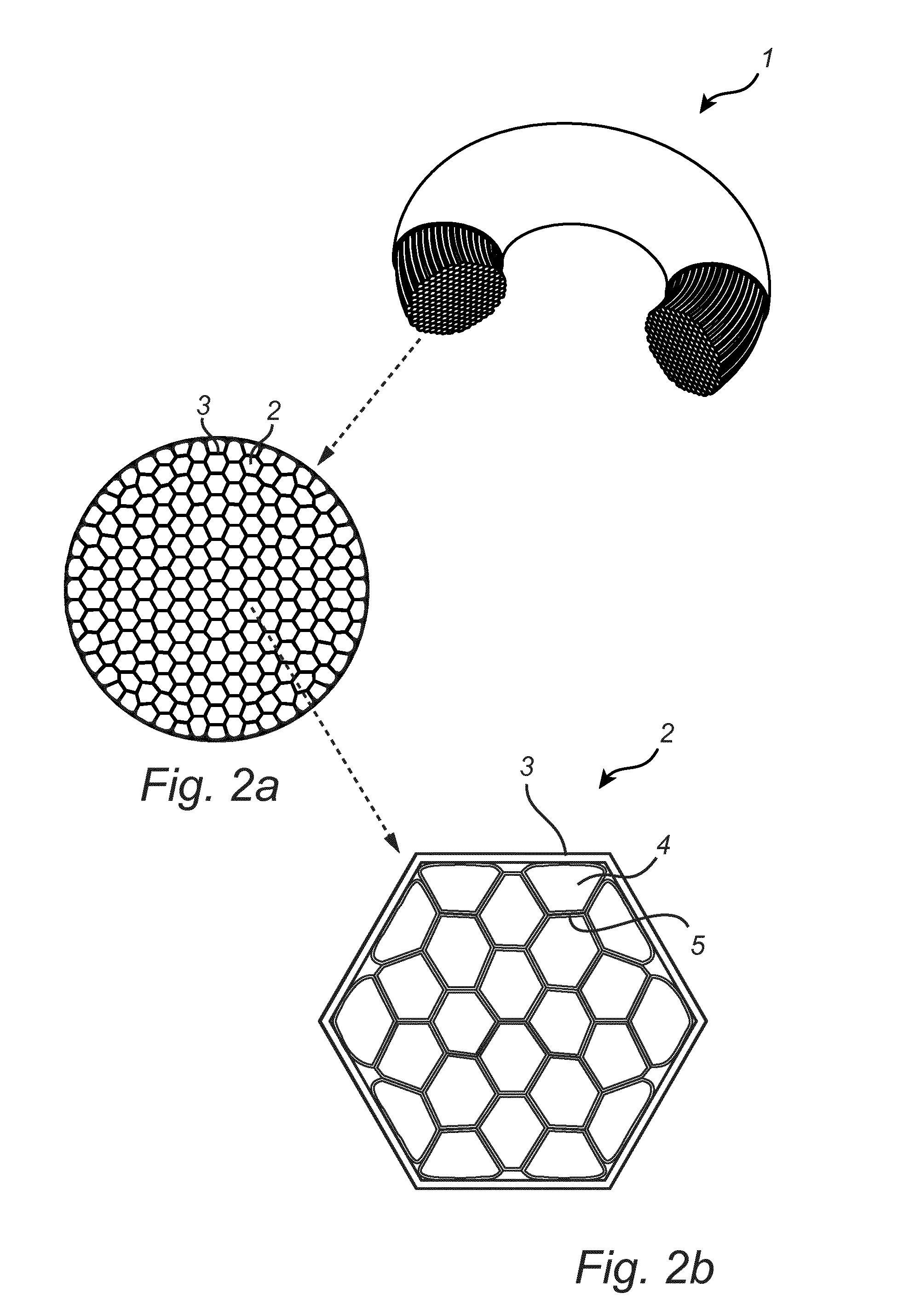
[0037]FIG. 1 shows a perspective view of a coil 1 for an inductor. The coil 1 is torus shaped and is built up by a wounded wire 2, better seen in the cross section of the coil shown in FIG. 2a. The coil is coated or wound with an insulated layer 11. In FIG. 2a it can be seen how the wire 2 has an insulating layer 3, and how the wire laps in the coil 1 have been compressed so that the shape of each inner wire lap is hexagonal, filling substantially all space, so that voids are reduced substantially. FIG. 2a further shows how the external wire layer of the coil is formed after the desired toroidal shape of the total coil so that the external wire layer follows the smooth toroidal torus shape of the coil 1. FIG. 2b shows an enlarged view of the cross sectional view of FIG. 2a showing the strands 4 of the wire 2. The strands 4 of the wire 2 are coated with a thin layer 5 of e.g. a polymer or resin to insulate the strands from one another.

[0038]FIG. 3 is a perspective view of an inductor...


PUM

PropertyMeasurementUnit
frequenciesaaaaaaaaaa
isostatic pressureaaaaaaaaaa
electrically insulatingaaaaaaaaaa

Abstract

The present invention relates to a coil (1) for an inductor (6), comprised by metal wire (2) wound circular around a centre axis (C), wherein the wire has an electrically insulating layer (3) insulating each turn of the wire in the winding from neighbouring turns,the shape of the complete winding, building up the coil (1), is substantially toroidal having a substantially elliptic cross section, wherein the thermal heat conductivity is above 1 W/m*K more preferably above 1,2 and most preferably above 1,5. The invention further relates to a magnetic core (7) suitable for an inductor (6), where in the core is made of a soft magnetic composite material made of metallic particles and a binder material, said particles are in the range of 1μm-1000 μm, particles that are larger than 150 are coated with a ceramic surface to provide particle to particle electrical insulation, wherein the volume of magnetic, metallic particles to total core volume is 0,5-0,9. The invention still further relates to an inductor (6) being a combination of said coil (1) and core (7), wherein the substantially all of said particles in the core are magnetically aligned with the magnetic field of the coil. The invention still further relates to the manufacturing methods of such a coil (1) and core (7).

Description

TECHNICAL FIELD[0001]The present invention relates generally to an optimal inductor design. More particularly, the present invention relates to a coil for an inductor as defined in the introductory parts of claim 1, a core for an inductor as defined in the introductory parts of claim 6, and an inductor comprising that coil and that core as defined in the introductory parts of claim 8. The invention further relates to a method for producing said coil and said core as defined in the introductory parts of claims 13 and 15.BACKGROUND ART[0002]With the ever growing power electronics industry, inductors have become increasingly important in applications such as power generation, power quality, AC drives, regenerative drives etc. Inductors are often key components in the equipment used and often determine the efficiency and performance of the equipment in question. An especially problematic area has been in applications where the inductor must handle at the same time a fundamental frequenc...

Claims


Application Information

Patent Timeline
Patent Type & Authority Applications(United States)
IPC IPC(8): H01F5/06H01F41/06H01F41/02H01F27/28H01F27/32
CPCH01F5/06H01F27/2823H01F41/0654H01F41/0246H01F27/32H01F3/08H01F5/00H01F17/04H01F27/255H01F27/2876H01F41/0273H01F41/12H01F41/073Y10T29/49071
Inventor BJARNASEN, OSCAR H.CEDELL, TORD
Owner COMSYS
Why Eureka
Try Eureka