Superconducting magnet coil system with quench protection for the prevention of excessive localized currents

a superconducting magnet coil and localized current technology, applied in the direction of superconducting magnets/coils, emergency protective arrangements for limiting excess voltage/current, reradiation, etc., can solve the problem of superconducting magnet coil system being jeopardized, superconducting magnet coil system being damaged, superconducting heat generation localized, etc. problem, to achieve the effect of high critical magnetic field, high magnetic field strength, and simple construction

Active Publication Date: 2011-03-17
BRUKER BIOSPIN
View PDF7 Cites 18 Cited by
  • Summary
  • Abstract
  • Description
  • Claims
  • Application Information

AI Technical Summary

Benefits of technology

[0026]In an alternative embodiment, the radially outermost main coil section of the superconducting high field magnet coil system is bridged with its own quench protection element. This design may simplify the construction, in particular, the wiring of the main coil sections. Typical quench protection elements are ohmic resistances or protective diodes.
[0027]In a further advantageous embodiment of the inventive superconducting high field magnet coil system, a first superconducting material of a conductor of the first main coil section has a higher critical magnetic field than a second superconducting material of a conductor of the second main coil section. The magnet coil system of this design can generate extremely high magnetic field strengths. The first material is more at risk due to possible larger excess currents or mechanical forces and local generation of heat, which can, however be selectively compensated for by the inventive loop interwiring.

Problems solved by technology

A superconducting magnet coil system is jeopardized by a sudden breakdown of the superconductivity (quench).
In case of a quench, the resistance of the magnet coil increases enormously, causing high electric voltages at that location which can damage the superconductor.
When the current in the magnet coil is not reduced quickly enough, the superconductor can burn through due to local generation of heat.
These excess currents can cause unacceptable excessive (Lorentz) forces which can mechanically destroy the conductor.
When a superconductor which is loaded with a high current quenches, there is also the danger that, when superconductivity breaks down, the then resistively flowing current generates so much heat that the superconductor burns out.
However, the high voltages in case of a quench cannot be prevented.
These high voltages would reach an unacceptable magnitude mainly for highest-field magnet systems, since these systems use superconducting material which must be insulated with a material having a low dielectric strength (e.g. glass fiber fabric).
This method entails large constructive and productional expense for connecting the radially widely spaced apart coil sections in pairs.
However, excessive Lorentz forces due to excess currents in the separately protected main coil sections remain problematic in the radially inner main coil area.

Method used


Image

  • Superconducting magnet coil system with quench protection for the prevention of excessive localized currents
  • Superconducting magnet coil system with quench protection for the prevention of excessive localized currents
  • Superconducting magnet coil system with quench protection for the prevention of excessive localized currents

Examples


Embodiment Construction

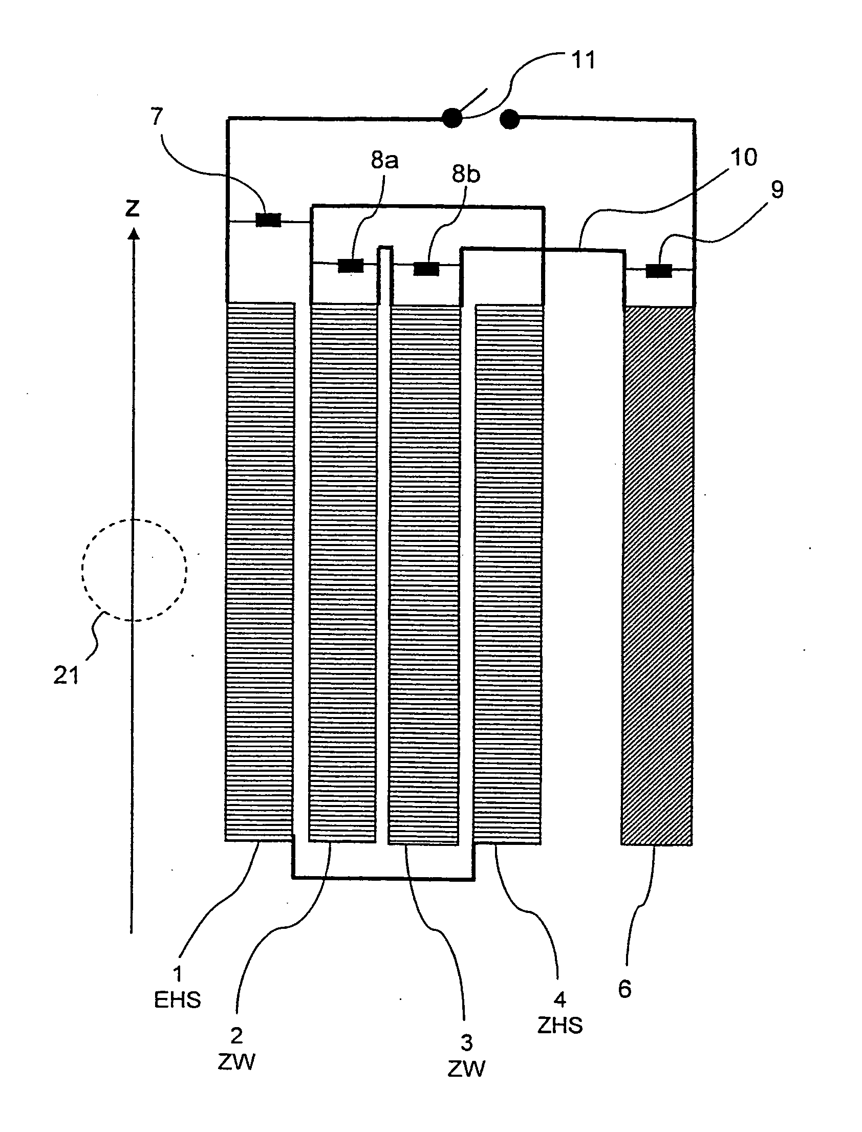
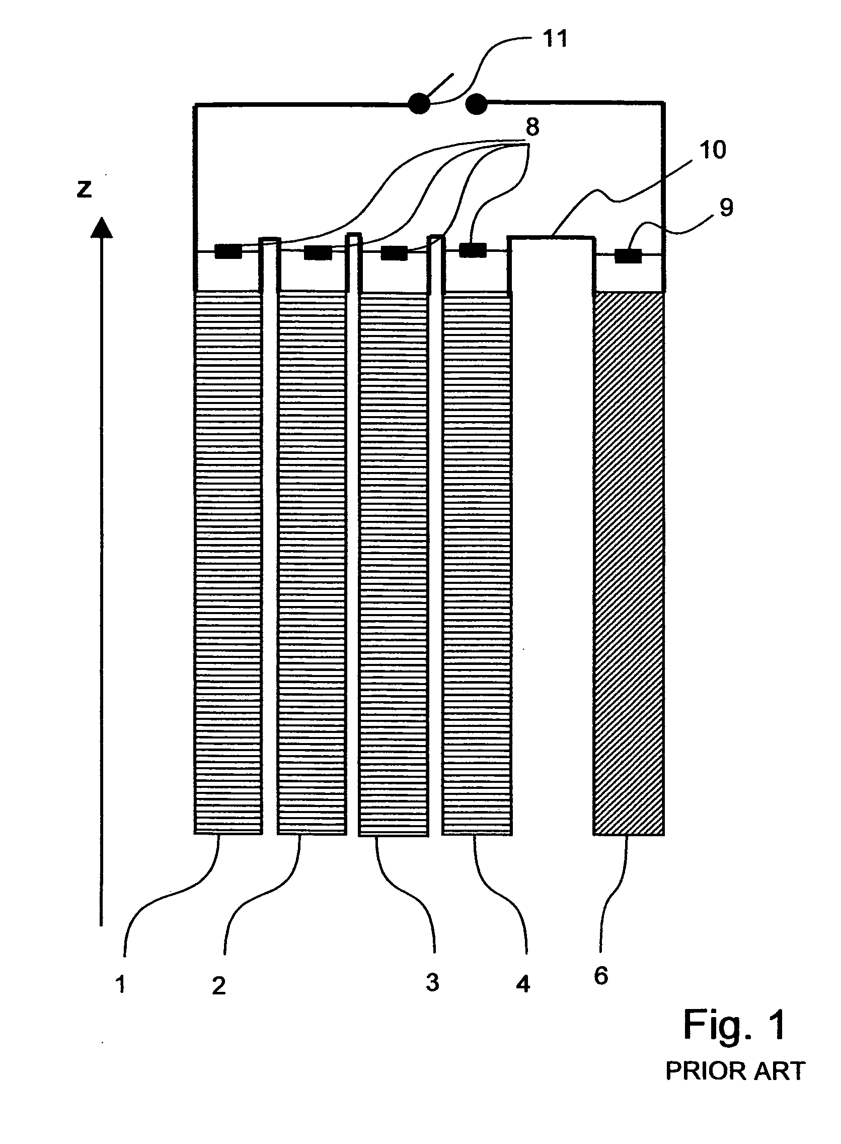
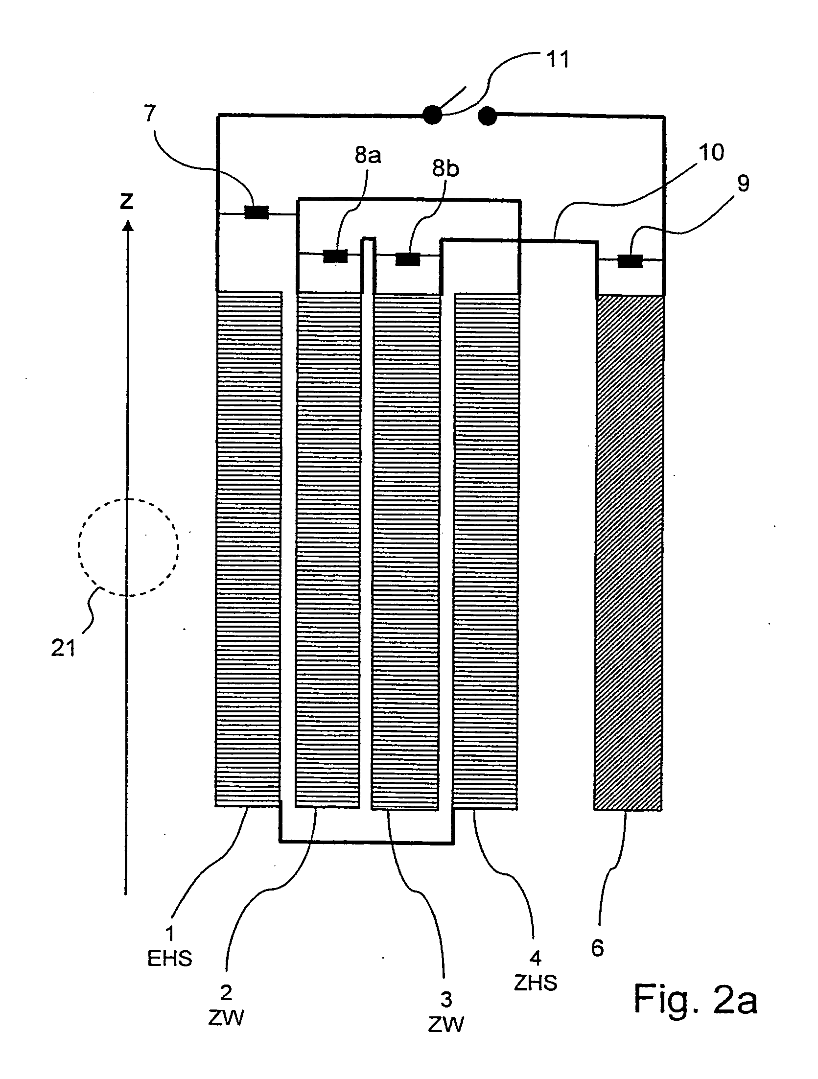
[0050]FIG. 1 shows a magnet coil system according to prior art (e.g. according to Wilson, l.c) with a main field coil which is disposed about an axis z, consisting of the main coil sections 1, 2, 3, 4 and with a shielding coil 6 which radially surrounds the main field coil. It should be noted that essentially only the right-hand half of the magnet coil system is illustrated (which also applies for the other figures) for reasons of simplicity. The main field coil and the shielding coil 6 can be superconductingly short-circuited via a superconducting main switch 11. The main field coil and the shielding coil 6 are connected in series via a superconducting electrical connection 10. The main coil sections 1, 2, 3, and 4 are each separately protected by a protective resistance 8. The shielding coil 6 is also protected by its own protective resistance 9.

[0051]At least the innermost main coil section 1 of the main field coil of superconducting high-field magnet systems regularly contains a...


PUM

PropertyMeasurementUnit
superconductingaaaaaaaaaa
quench protection resistanceaaaaaaaaaa
critical magnetic fieldaaaaaaaaaa

Abstract

A superconducting high-field magnet coil system comprising several radially nested main coil sections (1, 2, 3, 4, 5) which are connected to each other in series in such a fashion that currents of the same direction flow through them during operation, wherein a first main coil section (EHS) is disposed radially further inward than a second main coil section (ZHS) and at least one intermediate main coil section (ZW) is disposed radially between the first and the second main coil section (EHS, ZHS), and with a superconducting switch (11) via which all main coil sections (1, 2, 3, 4, 5) can be superconductingly short-circuited in series, is characterized in that the first main coil section (EHS) and the second main coil section (ZHS) are directly successively series-connected and the first main coil section (EHS) and the second main coil section (ZHS) are bridged by a common quench protection element, which does not bridge the at least one intermediate main coil section (ZW). The magnet coil system realizes quench protection for selectively preventing excess currents in magnet coil areas in which the excessive mechanical force load associated with an excess current would damage the superconductor.

Description

[0001]This application claims Paris Convention priority of DE 10 2009 029 379.5 filed Sep. 11, 2009 the complete disclosure of which is hereby incorporated by reference.BACKGROUND OF THE INVENTION[0002]The invention concerns a superconducting high-field magnet coil system comprising[0003]several radially nested main coil sections which are connected to each other in series in such a fashion that currents flow through them during operation in the same direction,wherein a first main coil section is disposed radially further inward than a second main coil section, and at least one intermediate main coil section is disposed radially between the first and the second main coil section,[0004]and with a superconducting switch via which all main coil sections can be superconductingly short-circuited in series.[0005]A magnet coil system of this type is disclosed in US 2008 / 0007375 A1.[0006]Superconducting magnet coil systems are used, in particular, for generating large magnetic field strengt...

Claims


Application Information

Patent Timeline
Patent Type & Authority Applications(United States)
IPC IPC(8): G01R33/035H01L39/08G01R33/3815H01F6/02
CPCG01R33/288H01F6/02G01R33/3815
Inventor FRANTZ, WOLFGANGNEUBERTH, GERALDROTH, GERHARD
Owner BRUKER BIOSPIN
Why Eureka
Try Eureka