
Axially-oriented cellular seal structure for turbine shrouds and related method

a technology of cellular seals and turbine blades, which is applied in the direction of blade accessories, machines/engines, waterborne vessels, etc., can solve the problems of major loss sources and excessive mixing losses, and achieve the effect of reducing mixing losses

Active Publication Date: 2011-10-13
GENERAL ELECTRIC CO
View PDF7 Cites 6 Cited by
  • Summary
  • Abstract
  • Description
  • Claims
  • Application Information

AI Technical Summary

Benefits of technology

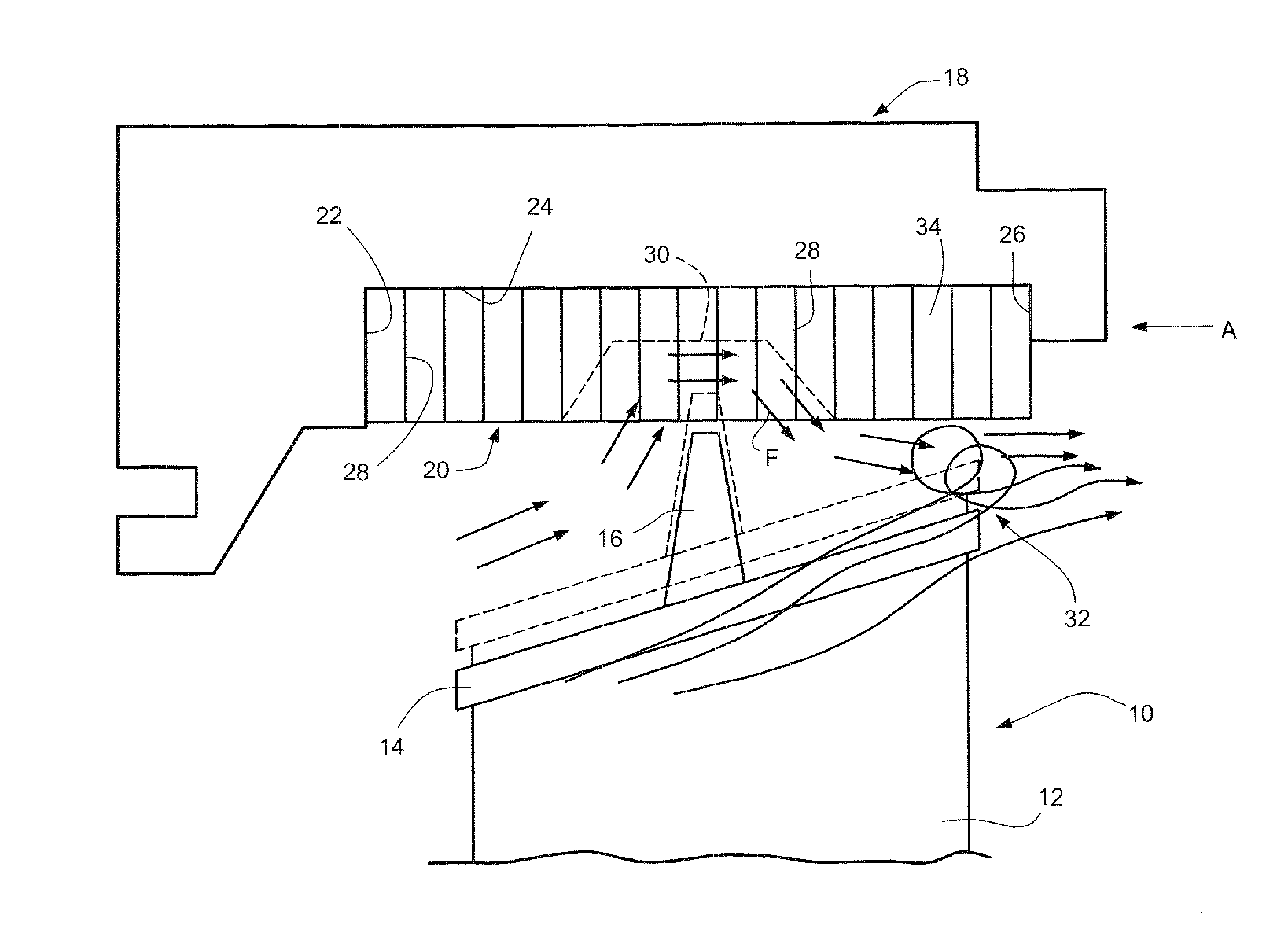
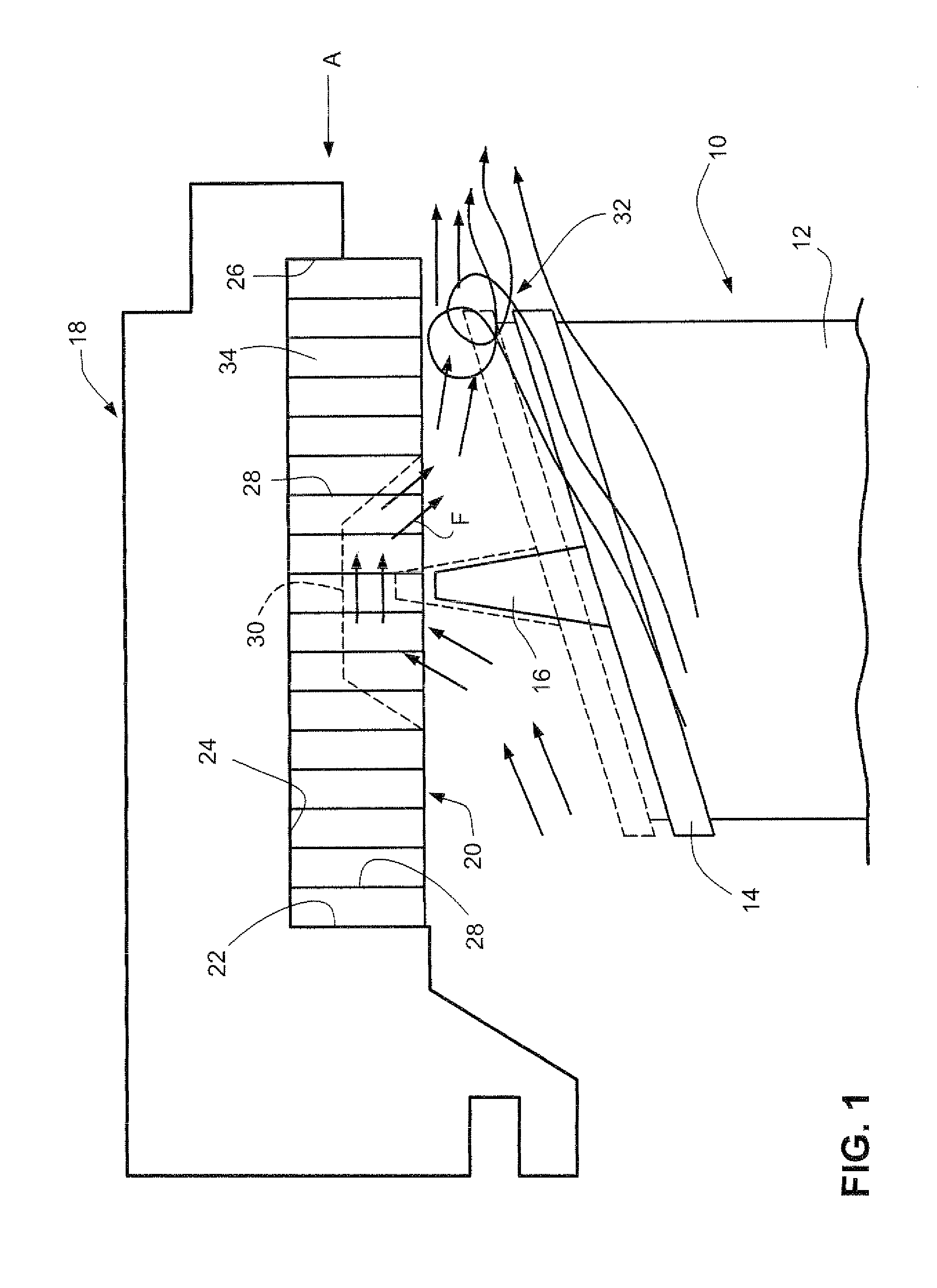
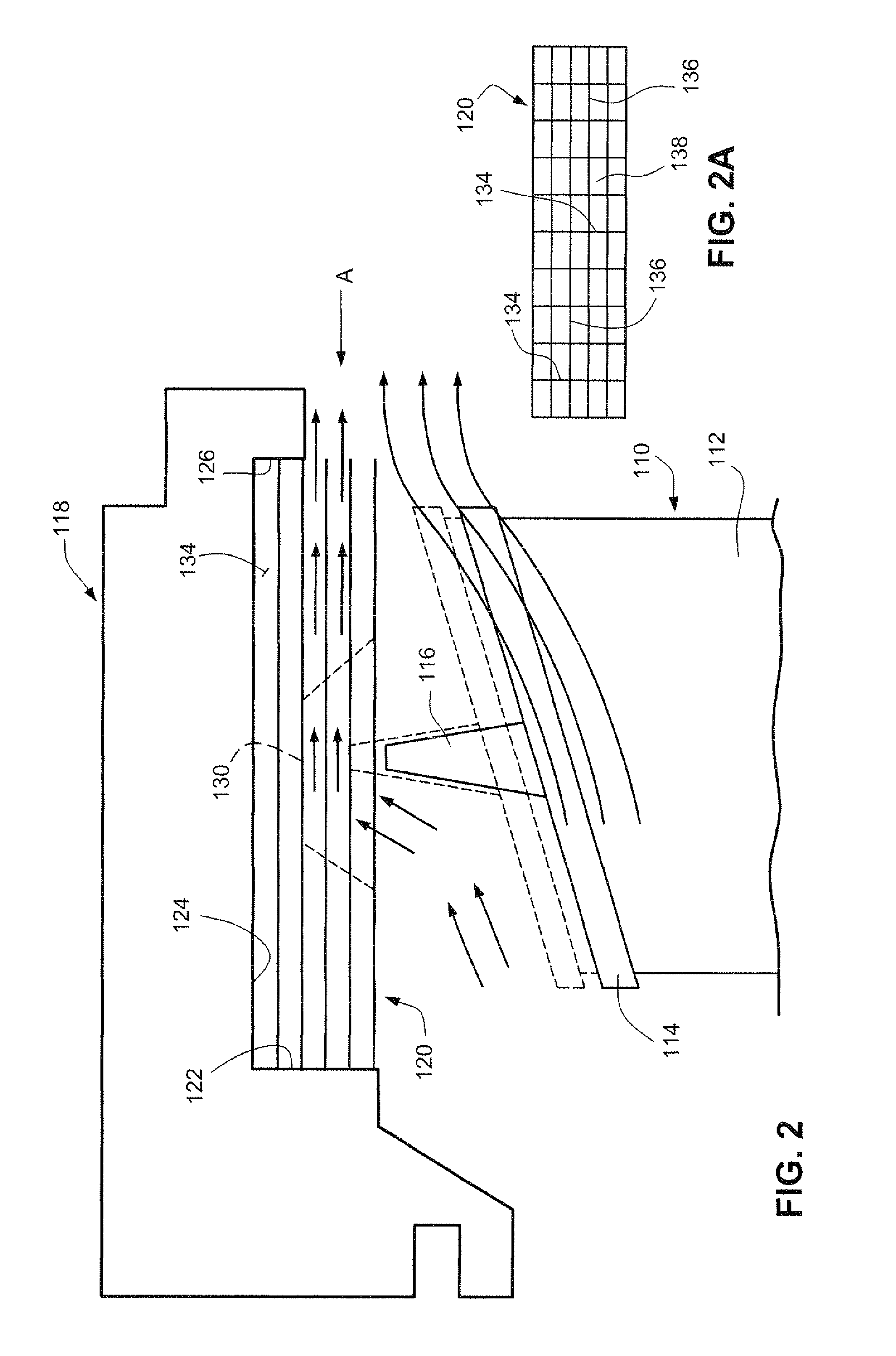
[0006]In still another exemplary but nonlimiting aspect, the invention provides a method of reducing mixing losses caused by tip leakage flow at a bucket tip / shroud-stator seal interface mixing with a main flow of combustion gases in a turbine engine, the method comprising: providing a cellular seal structure in a stator surface surrounding an annular bucket tip shroud; providing a rail on the radially outer surface of the bucket tip shroud adapted to penetrate the cellular seal structure during transient operating conditions of the turbine engine due to differential thermal expansion properties of the rotor and stator; and forming the cellular seal structure to include an annular array of individual cells arranged to provide substantially horizontal, closed-periphery flow passages extending continuously and unobstructed between forward and aft ends of the seal structure so that, upon penetration of the seal structure by the rail, tip leakage flow around the tip shroud will be confined to the substantially horizontal, closed-periphery flow passages and thus be prevented from turning radially inwardly into the main flow along an entire axial length dimension of the seal structure.

Problems solved by technology

The high energy flow escaping over the bucket tips and its subsequent interaction with the downstream main flow is one of the major sources of loss in the turbine stage.
Due to the inherent shape of the groove cut in the honeycomb seal structure, the overtip leakage flow turns downward (i.e., radially inward) and penetrates deep into the main flow path causing excessive mixing losses.
In addition, the turning inward of high temperature, overtip leakage flow due to the groove shape and honeycomb seal configuration, causes the tip leakage flow to touch the aft side of the bucket tip shroud, exposing it to a relatively hotter operating environment compared to a non-grooved seal configuration.

Method used


Image

  • Axially-oriented cellular seal structure for turbine shrouds and related method
  • Axially-oriented cellular seal structure for turbine shrouds and related method
  • Axially-oriented cellular seal structure for turbine shrouds and related method

Examples


Embodiment Construction

[0015]Referring now to FIG. 1, a typical tip-shrouded turbine bucket 10 includes an airfoil 12 which is the active component that intercepts the flow of gases and converts the energy of the gases into tangential motion. This motion, in turn, rotates the rotor to which the buckets 10 are attached.

[0016]A shroud 14 (also referred to herein as a “tip shroud”) is positioned at the tip of each airfoil 12 and includes a plate supported toward its center by the airfoil 12. The tip shroud may have various shapes as understood by those skilled in the art, and the exemplary tip shroud as illustrated here is not to be considered limiting. Positioned along the top of the tip shroud 14 is a seal rail 16 which minimizes passage of flow path gases through the gap between the tip shroud and the inner surface of the surrounding components. The rail 16 typically provided with a cutting tooth (not shown) for a purpose described below.

[0017]As shown in FIG. 1, the surrounding stationary stator shroud 1...


PUM

PropertyMeasurementUnit
degree anglesaaaaaaaaaa
rotationaaaaaaaaaa
angleaaaaaaaaaa

Abstract

A seal system between a row of buckets supported on a machine rotor and a surrounding stationary casing or stator includes a tip shroud secured at radially outer tips of each of the buckets, the tip shroud formed with a radially-projecting rail. A cellular seal structure is supported in the stationary stator in radial opposition to the tip shroud and the rail. The seal structure has an annular array of individual cells formed to provide continuous, substantially horizontal flow passages devoid of any radial obstruction along substantially an entire axial length dimension of the cellular seal structure to prevent flow about the tip shroud from turning radially inwardly.

Description

BACKGROUND OF THE INVENTION[0001]This present invention relates generally to turbines and turbine blades and more particularly, to tip-shrouded turbine blades and associated cellular seal structures.[0002]An axial gas turbine stage consists of a row of stationary blades followed by a row of rotating blades or buckets in an annulus defined by the turbine casing or stator. The flow is partially expanded in the vanes which direct the flow to the rotating blades where it is further expanded to generate required power output. For safe mechanical operation, there exists a minimum physical clearance requirement between the tip of the rotating blade and the casing or stator wall. Honeycomb strips on the casing wall are generally used to minimize running tip clearance of the rotating bucket at all operating conditions. To achieve tighter clearance, a rail on the tip shroud is allowed to rub and cut a groove in the honeycomb strip during transient operations. The shape and depth of this groov...

Claims


Application Information

Patent Timeline
Patent Type & Authority Applications(United States)
IPC IPC(8): F16J15/447B23P11/00
CPCF01D11/127Y10T29/49826F05D2250/283
Inventor JOHN, JOSHYJAIN, SANJEEV KUMARSUTHAR, RAJNIKUMAR NANDALAL
Owner GENERAL ELECTRIC CO
Learn More