Mobile docking station

a mobile docking station and docking station technology, applied in the field of mobile docking stations, can solve the problems of increasing the demand on the device for high-speed file transfer and high-speed streaming of critical real-time data, placing power burden and data throughput burden on the existing mobile devices, and achieving the effect of convenient handheld and high data ra

Inactive Publication Date: 2011-10-13
STELLAR TRUST
View PDF7 Cites 45 Cited by
  • Summary
  • Abstract
  • Description
  • Claims
  • Application Information

AI Technical Summary

Benefits of technology

The mobile docking station has a compact form, which makes it easily handheld, and is attachable to a variety of small mobile devices, such as smart phones, media players, and the like. The mobile docking station provides a platform for delivery and display of short range, multi-gigabit data, video, and audio to a receptive object within range, either indoors or outdoors. A Matrix Chip contains an energy-informed film that acts as a filter between the human body and sources of electronic radiation (EMR) to shield the user from harmful effects of electromagnetic energy generated by the attached electronic mobile device. A solar panel chip stores, recharges, and harvests wireless light energy to power the unit and attached mobile devices. The wireless mobile docking station electronically connects to the docked equipment to provide 60 GHz communication at very high data rates.

Problems solved by technology

These advanced applications have placed a power burden and data throughput burden on the existing mobile devices.
For example, the display screens of the mobile devices are small enough to possibly cause eyestrain when viewed for long periods of time.
Moreover, the advanced applications, coupled with the user's tendency to have these mobile devices powered up for long periods of time, have resulted in frustration among the users, in that they must schedule time-out periods in which their devices are tethered for recharging and, thus, not mobile during the time-out period.
Another source of frustration among users is the ever-increasing demand upon their devices for high-speed file transfer and high speed streaming of critical real-time data.

Method used


Image

  • Mobile docking station
  • Mobile docking station
  • Mobile docking station

Examples


Embodiment Construction

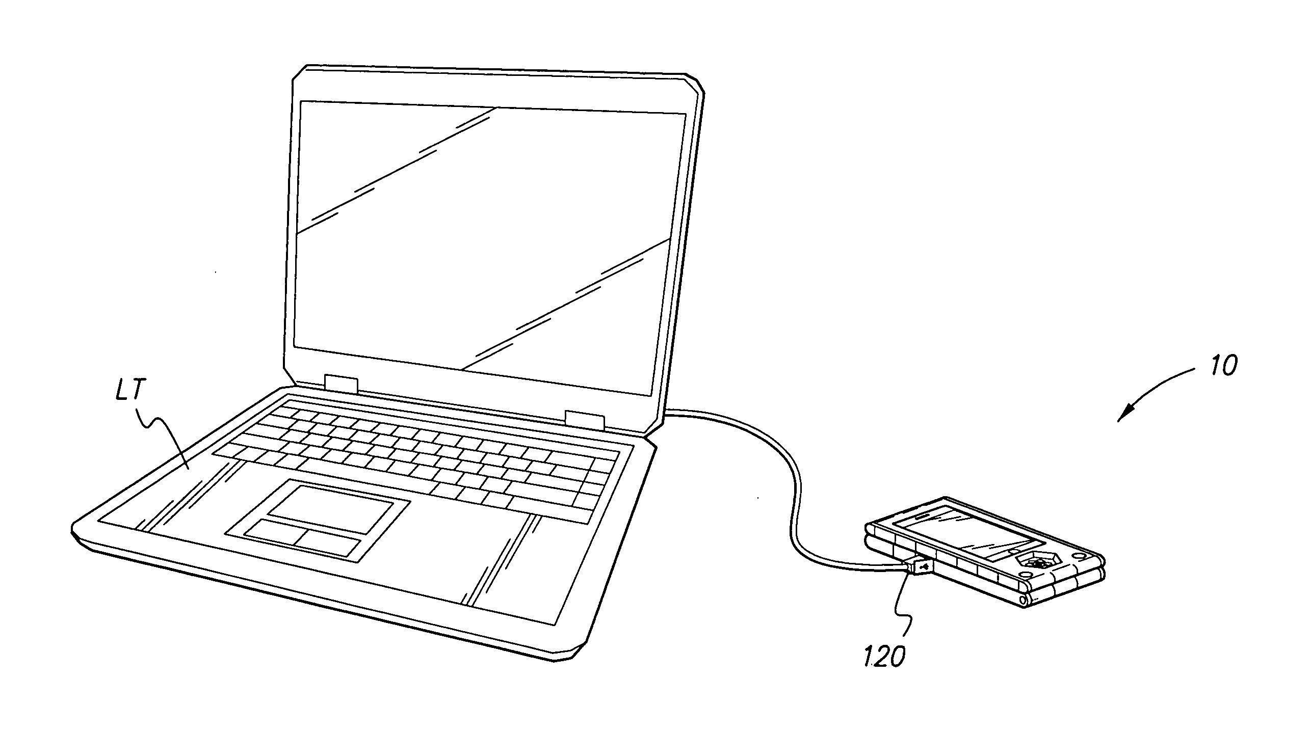
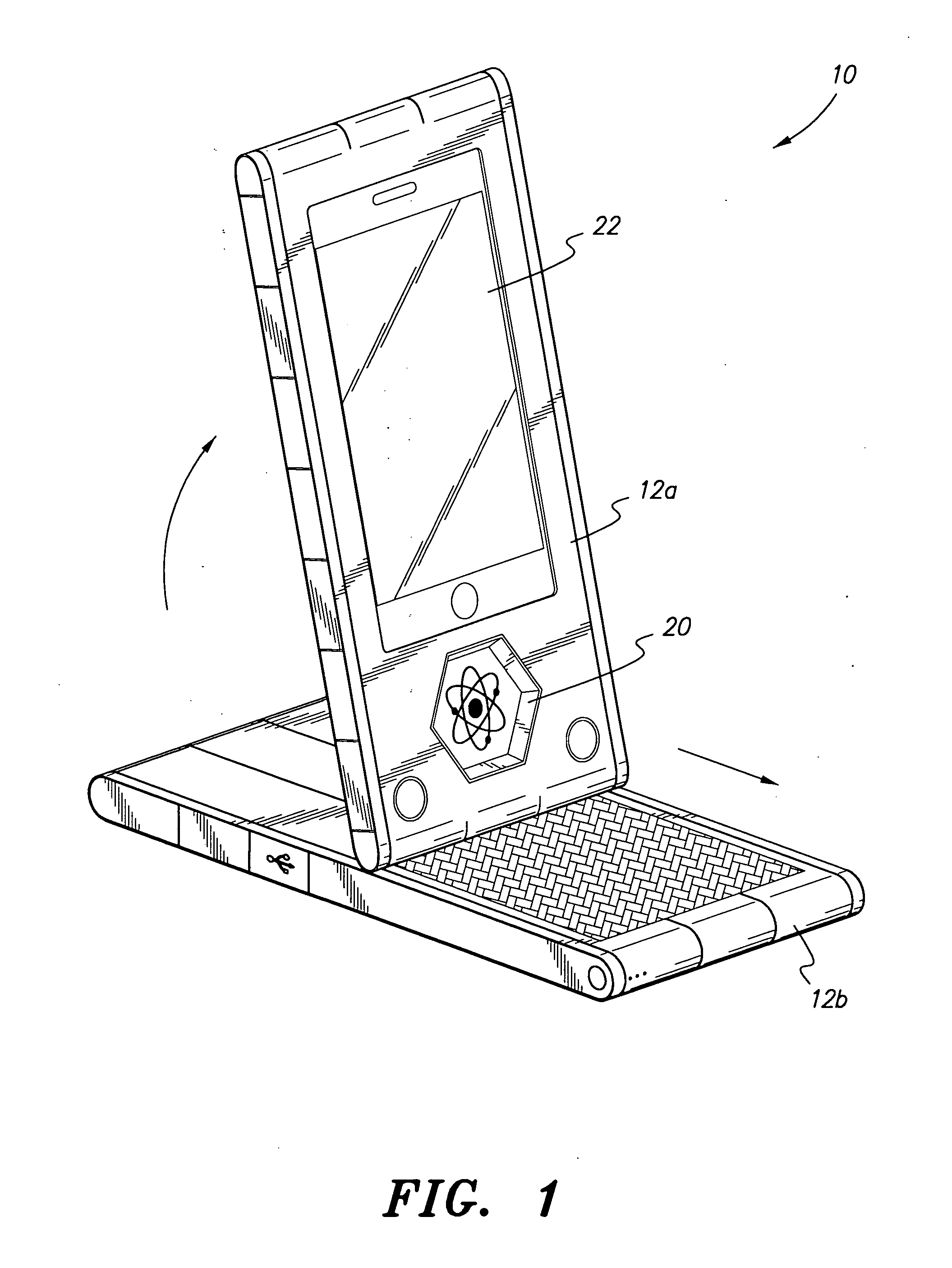
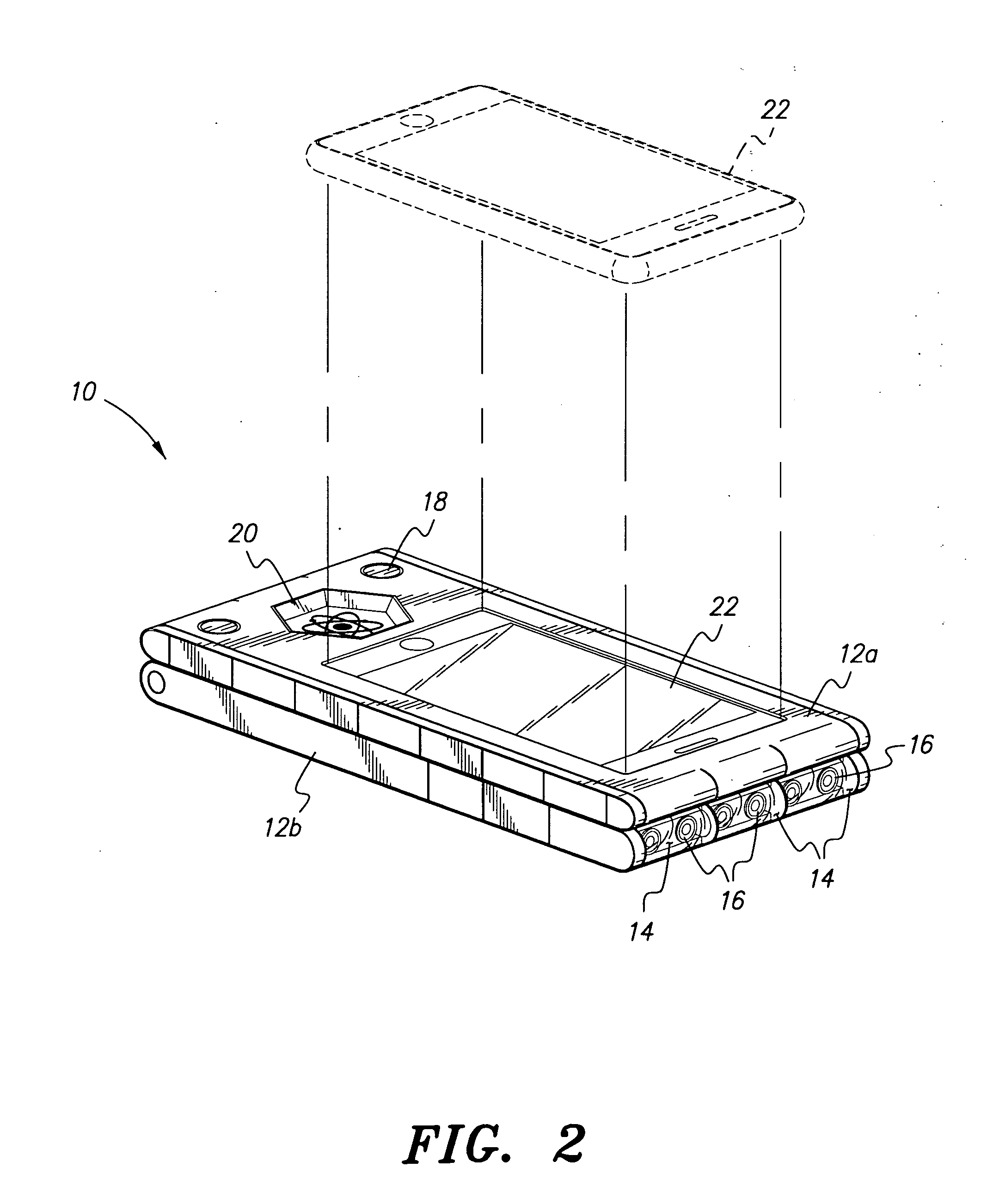
As shown in FIGS. 1 and 2, the mobile docking station 10 has a compact form, which makes it easily handheld, and attaches to a variety of small mobile devices, such as smart phones, media players, and the like. The mobile docking station 10 provides a platform for delivery and display of short range, multi-gigabit data, video, and audio to a receptive object within range, either indoors or outdoors. The docking station 10 comprises an upper mobile device docking housing 12a and a lower base housing 12b. Preferably the housings 12a and 12b are made of a titanium-based bulk metallic glass material. The upper docking housing 12a is adapted to receive, hold, and release smart phones, such as Apple IPhone, Google-Nexus One, Microsoft HD ZUNE Media Player, Nokia, and RIM (Blackberry). Image projectors 16, preferably using an RGB laser, are disposed in the front portion of the base housing 12b and are covered by clear projector covers 14. Dual circular members 18 are disposed on top of opp...


PUM

PropertyMeasurementUnit
frequenciesaaaaaaaaaa
volumeaaaaaaaaaa
angleaaaaaaaaaa

Abstract

The mobile docking station is compact, making it easily handheld, and attaches to a variety of small mobile devices, such as smart phones, media players, and the like. The mobile docking station provides a platform for delivery and display of short-range multi-gigabit data, video, and audio to a receptive object within range either indoors or outdoors. A Matrix Chip contains an energy-informed film that acts as a filter between the human body and sources of electronic radiation (EMR) to shield the user from harmful effects of electromagnetic energy generated by the attached electronic mobile device. A solar panel chip stores, recharges, and harvests wireless light energy to power the unit and attached mobile devices. The wireless mobile docking station electronically connects to the docked equipment to provide 60 GHz communication at very high data rates.

Description

BACKGROUND OF THE INVENTION1. Field of the InventionThe present invention relates to a mobile docking station having a charging mechanism and a high-speed data transceiver for an attached mobile electronic device.2. Description of the Related ArtMobile electronic devices, such as cellular phones, smart phones, media players and personal digital assistants (PDA's), are popular devices that are widely used. Advances in such mobile devices have included the addition of games, music, movies, and high-powered business applications for example. These advanced applications have placed a power burden and data throughput burden on the existing mobile devices. For example, the display screens of the mobile devices are small enough to possibly cause eyestrain when viewed for long periods of time. Moreover, the advanced applications, coupled with the user's tendency to have these mobile devices powered up for long periods of time, have resulted in frustration among the users, in that they must ...

Claims


Application Information

Patent Timeline
Patent Type & Authority Applications(United States)
IPC IPC(8): H01M10/46H02J17/00G03B21/00
CPCG03H1/2294H02J7/355H04M1/0214H04M1/0235H04M1/04C22C45/10H04M1/72533H04N9/3173G03H1/2249G03H2210/30H04M1/72527H02J7/35H04M1/72415H04M1/72409H04M1/72412
Inventor SMITH, FRANK R.LARK, DAVID L.
Owner STELLAR TRUST
Why Eureka
Try Eureka