Liquid Ejecting Apparatus and Control Method of Liquid Ejecting Apparatus

a liquid ejecting apparatus and control method technology, applied in the direction of printing, other printing apparatus, etc., can solve the problems of unfavorable image quality, unfavorable recording image bleeding, and unfavorable image quality, and achieve the effect of suppressing the variation of ejecting characteristics

Active Publication Date: 2011-10-13
SEIKO EPSON CORP
View PDF1 Cites 10 Cited by
  • Summary
  • Abstract
  • Description
  • Claims
  • Application Information

AI Technical Summary

Benefits of technology

[0009]An advantage of some aspects of the invention is that it provides a liquid ejecting apparatus in which it is possible to suppre

Problems solved by technology

Incidentally, since it is hard for the resin film to absorb ink, there is a risk of a recorded image bleeding.
Accordingly, there is a risk of the density of an image printed on the film vary undesirably.
As described above, where respective printed parts of an image are joined into one sheet, there is a problem where differences i

Method used


Image

  • Liquid Ejecting Apparatus and Control Method of Liquid Ejecting Apparatus
  • Liquid Ejecting Apparatus and Control Method of Liquid Ejecting Apparatus
  • Liquid Ejecting Apparatus and Control Method of Liquid Ejecting Apparatus

Examples


second embodiment

[0072]Next, the invention will be described.

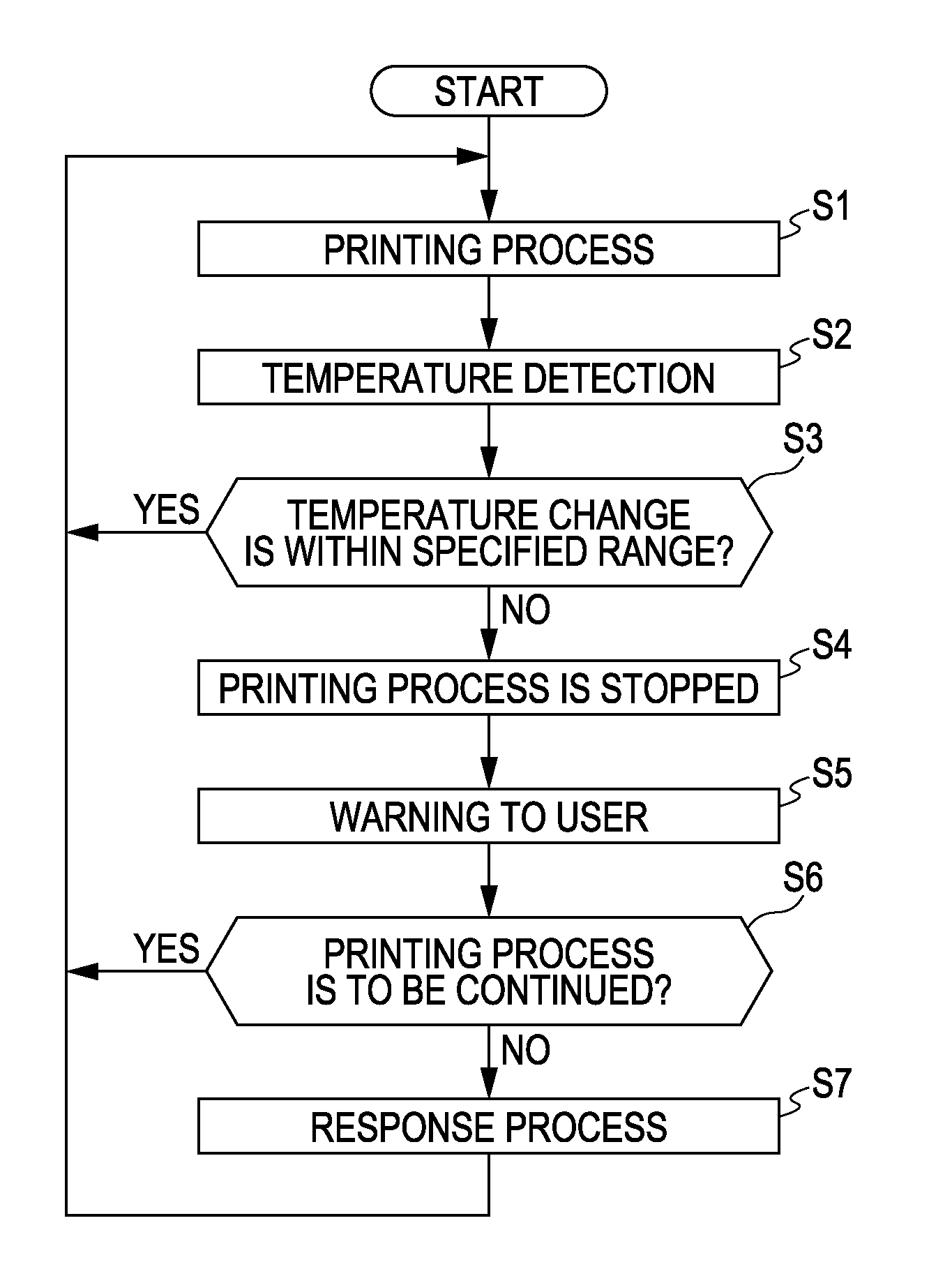
[0073]In this embodiment, it is different from the above-described first embodiment in that a flushing process (FL) is carried out as the response process (S7). Since the other points are the same as those in the first embodiment, an explanation thereof is omitted. The flushing process is to move the recording head 8 up to above the capping member 21 at the home position or the ink receiving section 23 provided at the full-position on the opposite side to the home position and then eject (ejection for ejection capability restoration not related to ejection for printing onto the printing medium S) ink from all of the nozzles 43 toward these liquid receiving sections, as described above. By performing the flushing process, new ink having a temperature within a predetermined range or a temperature close to a temperature within a predetermined range is introduced from an ink supply source such as an ink cartridge into an ink flow path in the r...

third embodiment

[0074]Next, the invention will be described.

first embodiment

[0075]In this embodiment, it is different from each of the above-described embodiments in that as the response process (S7), the recording head 8 moves outside the printing area, specifically, to the home position or the full-position, and then waits at the position. Since other points are the same as those in the first embodiment, an explanation is omitted. Since at least one of a change in temperature or the temperature of the recording head 8 exceeding a predetermined range is, in many cases, due to a change in temperature or the temperature of the recording head8 exceeding a predetermined range due to the heat of the platen 16 heated by the platen heater 10, by making the recording head 8 wait outside the printing area, it is hard for the heat from the platen heater 10 to be transmitted to the recording head 8, so that it is possible to lower the temperature of the ink in the recording head 8. Also, the ink can be prevented from being erroneously ejected onto the recording mediu...


PUM


Abstract

Liquid ejecting apparatus and control methods thereof are disclosed. A liquid ejecting apparatus includes an ejecting head having liquid-ejecting nozzles, a platen disposed to support a recording medium and face the ejecting head, a heater that heats the platen, a temperature sensor to detect a temperature of the ejecting head, and a control section that causes liquid to be ejected from the nozzles. If a change in a temperature of the ejecting head and/or a temperature of the ejecting head exceeds a predetermined range, the control section stops ejection of liquid for printing from the nozzles in the absence of a user input to continue printing. After the control section stops the ejection of liquid, a response process can be carried out.

Description

[0001]This application claims priority to Japanese Application No. 2010-092364, filed Apr. 13, 2010, the entirety of which is incorporated by reference herein.BACKGROUND[0002]1. Technical Field[0003]The present invention relates generally to a liquid ejecting apparatus such as an ink jet type printer and a control method thereof, and more particularly to a liquid ejecting apparatus having a heater that heats an ejection target, and a control method thereof.[0004]2. Related Art[0005]A typical liquid ejecting apparatus has a liquid ejecting head with nozzles operable to eject various liquids. As a representative example of a liquid ejecting apparatus, for example, image recording apparatuses can be given such as ink jet type printers (hereinafter simply referred to as printers), which are provided with ink jet type recording heads (hereinafter simply referred to as recording heads and can also be referred to as liquid ejecting heads which eject ink in the form of a liquid) and perform...

Claims


Application Information

Patent Timeline
IPC IPC(8): B41J29/38
CPCB41J2/04516B41J2/04563B41J2/04581B41J11/08B41J2/14274B41J11/002B41J2/0459B41J11/0024
Inventor MAKITA, SHUSHIOZAWA, KINYATANAKA, RYOICHI
Owner SEIKO EPSON CORP
Why Eureka
Try Eureka