
Color measuring apparatus and color measuring method

a color measuring and color technology, applied in the field of color measuring apparatus and color measuring method, can solve the problems of reducing color uniform performance, affecting accuracy, and taking an immense amount of time to perform setting operation for measurement, and achieve the effect of short time and high degree of accuracy

Inactive Publication Date: 2011-10-13
SEIKO EPSON CORP
View PDF2 Cites 14 Cited by
  • Summary
  • Abstract
  • Description
  • Claims
  • Application Information

AI Technical Summary

Benefits of technology

[0009]An advantage of some aspects of the invention is to provide a color measuring apparatus and a color measuring method which can set a measurement region for multipoint measurement with ease and in a short time.
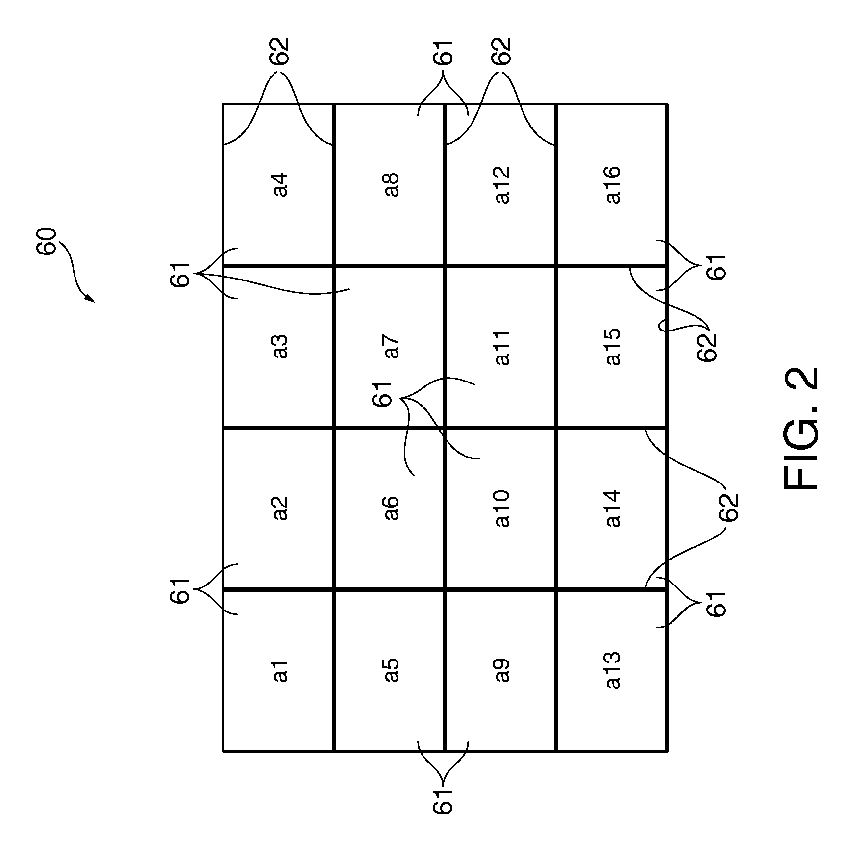
[0013]By doing so, a measured region in which the color is measured, the measured region in the measurement image, is automatically set by image processing by which the measurement regions in the teach image are recognized. This makes it possible to eliminate the need for input operation performed by the user to set a measured region by using a mouse or the like. Therefore, it is possible to set a large number of measured regions in a measurement image displayed on the display device with ease, and set measured regions for multipoint measurement with a high degree of accuracy and in a short time.
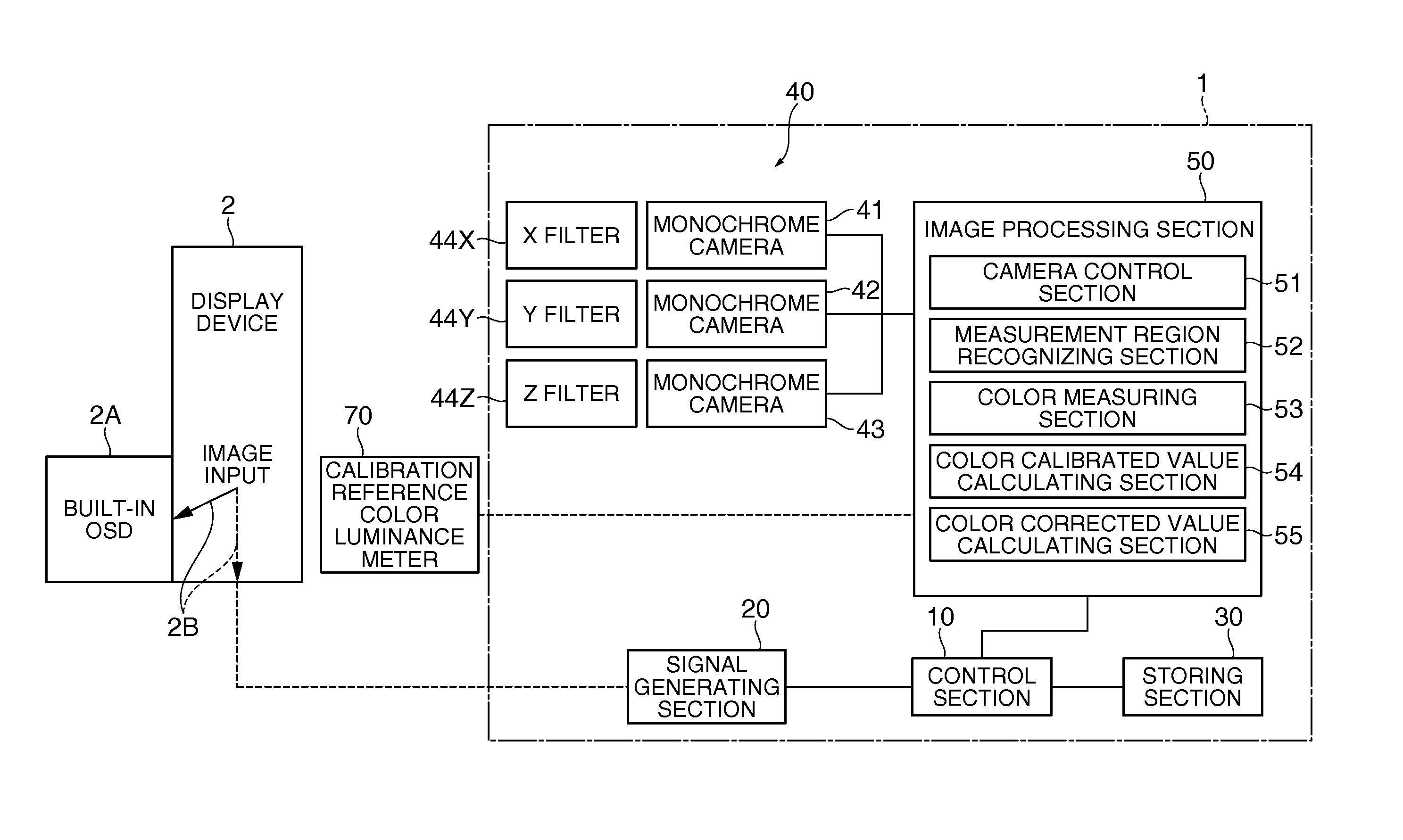
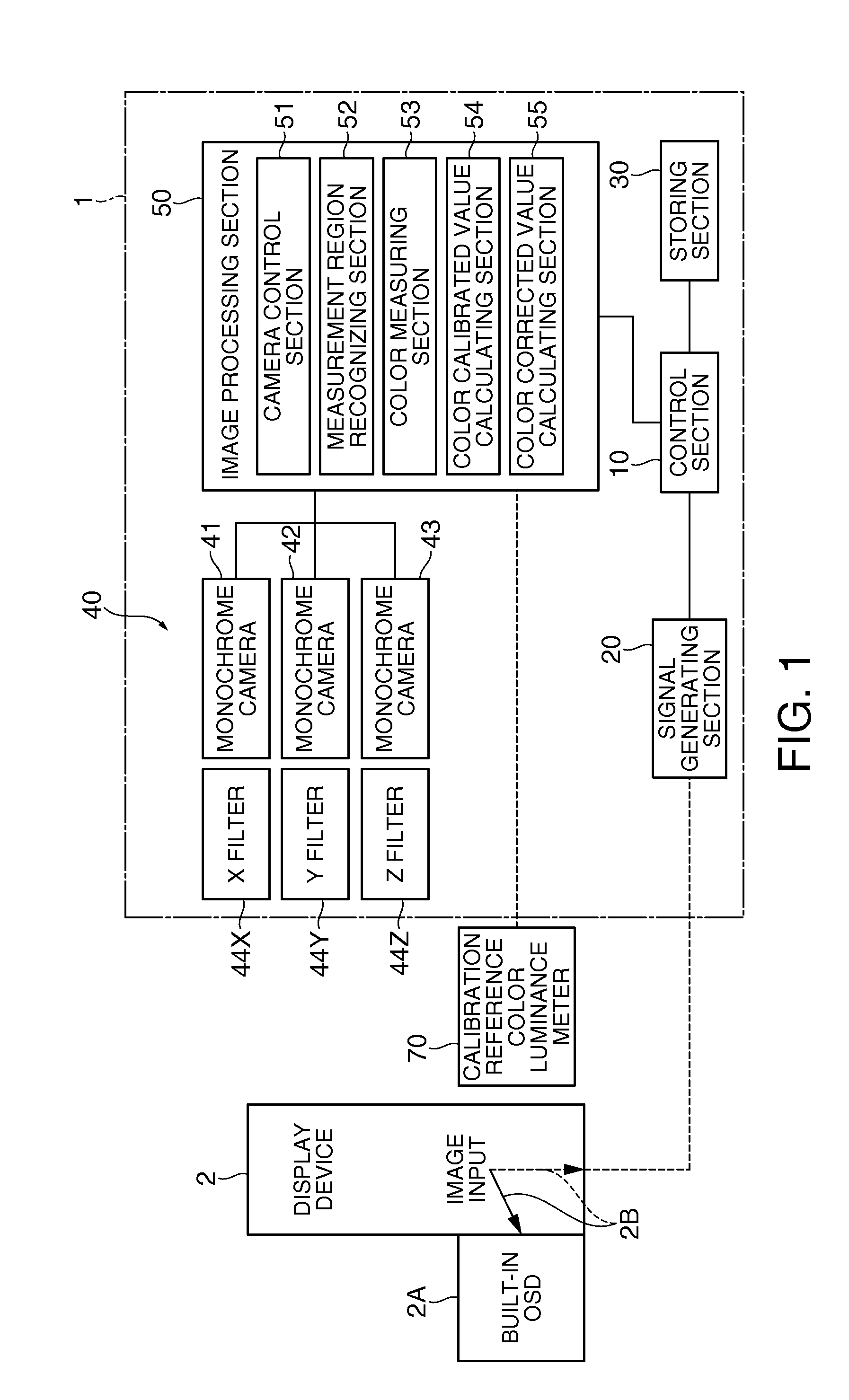
[0015]According to the aspect of the invention, images are taken concurrently by three cameras with three tristimulus filters, which are provided one for each of the three cameras. This eliminates the need to perform image scan operations sequentially in individual display colors, and makes it possible to shorten the amount of time. Furthermore, it is possible to prevent an increase in measuring time as a result of measurement being performed in individual display colors for one second or more in order to prevent the influence of flicker. As described above, since three tristimulus filters are provided, one for each of the three cameras, an inexpensive monochrome camera can be used also in color measurement, and it is also possible to shorten the measuring time.
[0018]Incidentally, since the reference colorimeter is used for calibration of the color measuring section, it is necessary simply to use the reference colorimeter at the start of measurement, and there is no need to use the reference colorimeter after the color calibrated value is obtained. Therefore, it is also possible to use a reference colorimeter, such as a spectroscopic color luminance meter, which can perform measurement with a high degree of accuracy, but requires a long measuring time. By obtaining a color calibrated value by using such a reference colorimeter, it is possible to correct the value measured by the color measuring section based on the measurement value obtained by the reference colorimeter, and obtain a more accurate color measurement value based on the color corrected value obtained by the correction.
[0022]This eliminates the need for input operation performed by the user to set a measured region in which the color is measured, the measured region in the measurement image, and makes it possible to set a large number of measured regions in a measurement image displayed on the display device with ease, and set measured regions for multipoint measurement with a high degree of accuracy and in a short time.

Problems solved by technology

This causes optical strains in a lamp serving as a light source, an electrooptic transducer, or an internal optical component, leading to a reduction of color uniform performance.
At this time, a user who desires to improve the accuracy of multipoint measurement sometimes sets and inputs hundreds of measurement locations, and it undesirably takes an immense amount of time to perform setting operation for measurement.
Moreover, it is very complicated to set a measurement location by input operation using a mouse without impairing accuracy.
Furthermore, it is more complicated and takes more time to set a deformed region, such as a circular or oval region, other than a rectangular region accurately.
As described above, with the existing measuring method, it undesirably takes an immense amount of time to perform setting operation for measurement.

Method used


Image

  • Color measuring apparatus and color measuring method
  • Color measuring apparatus and color measuring method
  • Color measuring apparatus and color measuring method

Examples


Embodiment Construction

[0033]Hereinafter, an embodiment of the invention will be described based on the drawings.

Configuration of Color Measuring Apparatus

[0034]As shown in FIG. 1, a color measuring apparatus 1 is an apparatus having a color measuring function of measuring the color of an image at multiple points, the image displayed on a display device 2 which is an object to be inspected.

[0035]The color measuring apparatus 1 includes a control section 10, a signal generating section 20 serving as an image display control section which generates a signal making the display device 2 display a predetermined image, a storing section 30, an image taking section 40 taking an image of the image displayed on the display device 2, and an image processing section 50 performing image processing on the taken image.

[0036]The control section 10 controls the signal generating section 20, the storing section 30, and the image processing section 50. That is, the control section 10 performs processing for measuring the c...


PUM


Abstract

A color measuring apparatus includes an image taking section; a signal generating section selecting a teach image in which a plurality of measurement regions are set or a measurement image for color measurement and making a display device display the selected image; a camera control section controlling the image taking section to make the image taking section take an image of the image displayed on the display device; a measurement region recognizing section recognizing the measurement regions by performing image processing on the teach image whose image was taken by the image taking section; and a color measuring section measuring the color of each of measured regions corresponding to the measurement regions recognized by the measurement region recognizing section, the measured regions in the measurement image whose image was taken by the image taking section.

Description

BACKGROUND[0001]1. Technical Field[0002]The present invention relates to a color measuring apparatus and a color measuring method.[0003]2. Related Art[0004]In the past, a color measuring apparatus provided with an RGB filter-equipped single-chip or three-chip color camera and an arithmetic unit which corrects the measurement value obtained by the camera has been used in order to inspect the quality of a display image of an image display device (JP-A-6-233333 (hereinafter referred to as Patent Document 1)).[0005]Moreover, a color measuring apparatus provided with a color camera with sequential tristimulus filters and a control apparatus which calculates the chromaticity by combining the image data of the tristimulus values has been known (JP-A-6-201472 (hereinafter referred to as Patent Document 2)). The tristimulus filters described in Patent Document 2 are each set in a circular folder and sequentially face a light receiving element as a result of the rotation of the folder.[0006]I...

Claims


Application Information

Patent Timeline
IPC IPC(8): H04N7/18
CPCG01J3/465G01J3/513G01J3/506
Inventor YAMAGISHI, EIICHI
Owner SEIKO EPSON CORP
Learn More