Four-dimensional polynomial model for depth estimation based on two-picture matching

a two-picture matching and depth estimation technology, applied in the field of camera depth estimation, can solve the problems of poor focusing decision of passive systems in low contrast or low, and many focusing systems perform poorly when the subject is present, and achieve the effect of accurate estimating subject distance and accurate estimation of subject distan

Active Publication Date: 2011-10-13
SONY CORP
View PDF0 Cites 41 Cited by
  • Summary
  • Abstract
  • Description
  • Claims
  • Application Information

AI Technical Summary

Benefits of technology

[0037]An element of the invention is an apparatus and method for accurately estimating subject distance in response to capturing two images at different focus settings (e

Problems solved by technology

Passive systems often make poor focusing decisions in low contrast or low light conditions.
In addition, many focusing systems perform poorly

Method used


Image

  • Four-dimensional polynomial model for depth estimation based on two-picture matching
  • Four-dimensional polynomial model for depth estimation based on two-picture matching
  • Four-dimensional polynomial model for depth estimation based on two-picture matching

Examples


embodiment 10

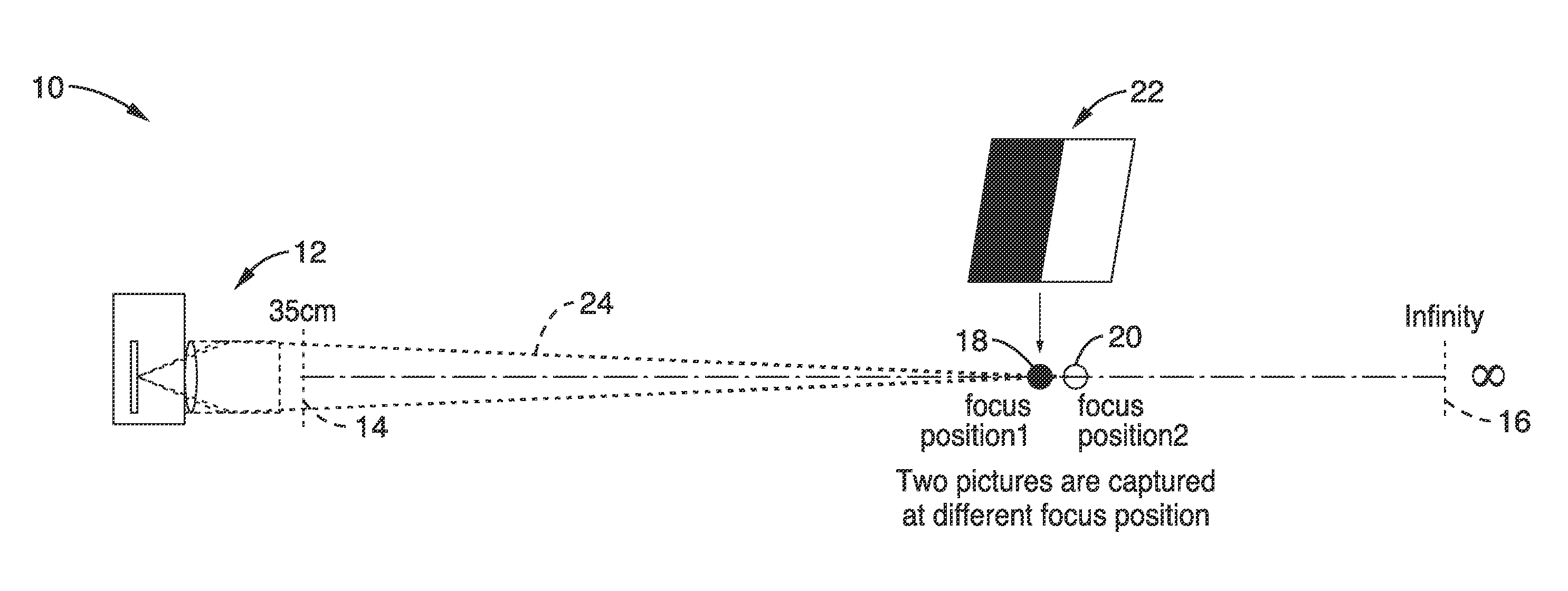
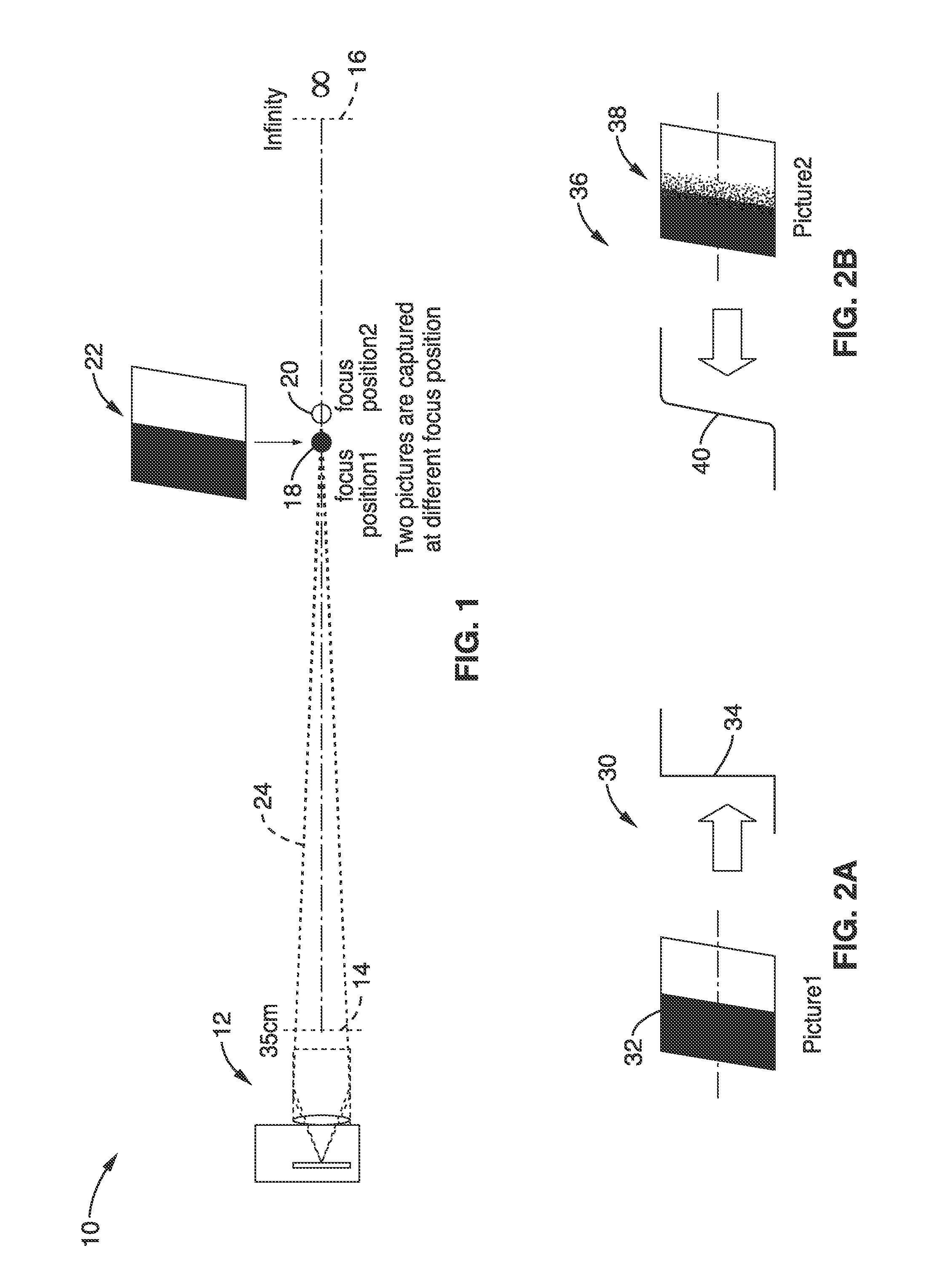
[0065]FIG. 1 illustrates an embodiment 10 of capturing images in the process of creating a set of matching curves to characterize a given camera-lens system, hereafter referred to simply as a camera. Multiple images are captured of a calibration target (or calibration subject), at different focus positions (subject-distances) when collecting a data set for a given imaging apparatus (e.g., specific embodiment, make or model of camera, or a family of cameras using the same / similar optical imaging elements). Collecting the data set comprises a characterization process for the camera-lens system at a given magnification setting (e.g., lens at a fixed focal length—“zoom” setting). An imaging device (camera) 12 is shown which can focus from a minimum focal distance 14 on out to infinity 16. Minimum focal distance 14 (e.g., in this case 35 cm) is shown as well as focus at infinity 16. According to the invention, the focus converges to a first focus position 18 and then to a second focus po...

embodiment 1

[0132]2. An apparatus as recited in embodiment 1, wherein said multiple object images comprise at least two images captured at different focus positions using an identical aperture setting and focal length.

[0133]3. An apparatus as recited in embodiment 1, further comprising programming executable on said computer processor for automatically adjusting focus of said apparatus in response to said estimation of subject distance.

[0134]4. An apparatus as recited in embodiment 1, wherein during said compensating for motion at least one block from the first image is located as a fit within the second image.

[0135]5. An apparatus as recited in embodiment 1, wherein said compensating for motion is configured for being performed in response to one or more convolutions by a blur kernel to determine blur difference.

[0136]6. An apparatus as recited in embodiment 1, wherein said compensating for motion is performed according to,

(x^v,y^v)=argmin(xv,yv)fi(x,y)-fj(x-xv,y-yv)

in which two images fi and ...

embodiment 6

[0137]7. An apparatus as recited in embodiment 6, wherein blur difference is determined in response to whether image fi or fj is sharper, and determined in response to,

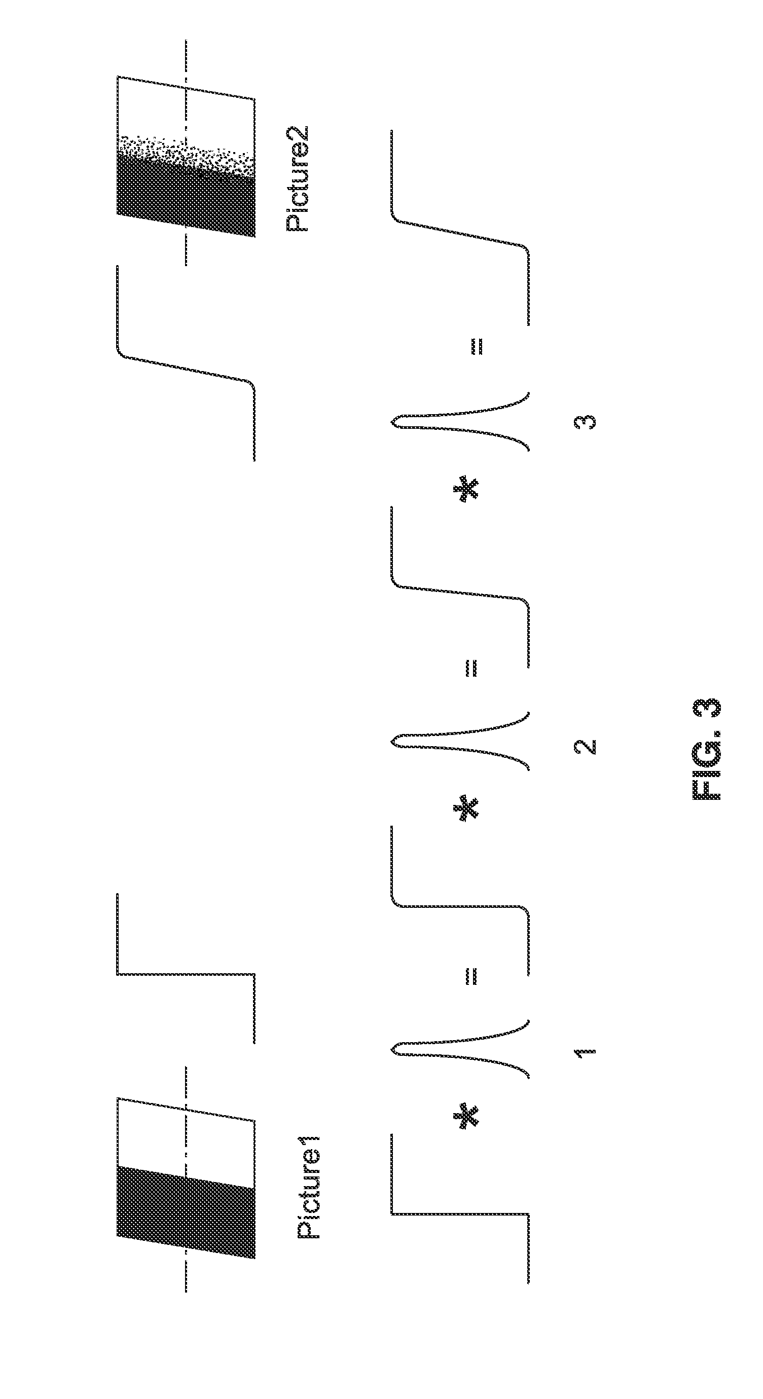
I1=argminIfi *K *K …*KIconvolutions-fjV,andI2=argminIfjV *K *K …*KIconvolutions-fi,

in which I1 and I2 are first and second blur difference values, fi and fj are the two images captured, fjV is the captured images in response to motion compensation, and K are blur kernels; wherein if I1 is larger than I2, then fi is sharper than fj, and the blur difference will be given by I1, otherwise if I2 is larger than I1, then I2 is sharper and the blur difference will be given by −I2; and wherein the sign of blur difference values indicates which image is sharper.

[0138]8. An apparatus as recited in embodiment 1, wherein said blur difference IA—B is computed as,

IA_B=min(xv,yv)[argminIfA(x,y) *K(x,y) *K(x,y) *…*K(x,y)Iconvolutions-fB(x-xv,y-yv)]

in which K are convolution operations, (x,y) is amount of pixel location shift, (xV,yV)...


PUM


Abstract

Camera depth estimation is performed in response to picture matching based on blur difference computed between images captured at different focal positions. A blur difference model is stored in the camera based on characterization of the camera with a series of matching curves in which blur difference varies depending on the focal length, aperture, subject distance, and lens focus position. A four-dimensional polynomial model is created to fit the matching curves for use in estimating subject distance. During operation, images are captured for use in estimating subject distance. Motion compensation is applied and blur difference is determined. Blur difference is utilized in the polynomial model to estimate subject distance. Subject distance estimates can be output or utilized within an auto focus process to provide accurate focus adjustments.

Description

CROSS-REFERENCE TO RELATED APPLICATIONS[0001]Not ApplicableSTATEMENT REGARDING FEDERALLY SPONSORED RESEARCH OR DEVELOPMENT[0002]Not ApplicableINCORPORATION-BY-REFERENCE OF MATERIAL SUBMITTED ON A COMPACT DISC[0003]Not ApplicableNOTICE OF MATERIAL SUBJECT TO COPYRIGHT PROTECTION[0004]A portion of the material in this patent document is subject to copyright protection under the copyright laws of the United States and of other countries. The owner of the copyright rights has no objection to the facsimile reproduction by anyone of the patent document or the patent disclosure, as it appears in the United States Patent and Trademark Office publicly available file or records, but otherwise reserves all copyright rights whatsoever. The copyright owner does not hereby waive any of its rights to have this patent document maintained in secrecy, including without limitation its rights pursuant to 37 C.F.R.§1.14.BACKGROUND OF THE INVENTION[0005]1. Field of the Invention[0006]This invention perta...

Claims


Application Information

Patent Timeline
IPC IPC(8): H04N5/232
CPCH04N5/23254H04N5/23212H04N23/67H04N23/6811
Inventor LI, PINGSHANWONG, EARLMIYAGI, KENSUKE
Owner SONY CORP
Why Eureka
Try Eureka