
LED lighting system

a lighting system and led light technology, applied in the field of led lighting systems, can solve the problems unreliable high-output lighting systems, and inconvenient installation, and achieve the effects of low power requirements, reduced heat emission and noise, and high outpu

Active Publication Date: 2011-10-13
SOCARRAS TITO
View PDF3 Cites 10 Cited by
  • Summary
  • Abstract
  • Description
  • Claims
  • Application Information

AI Technical Summary

Benefits of technology

[0003]The present invention relates generally to lighting systems and more specifically to various embodiments of a light-emitting diode (hereinafter referred to as “LED”) lighting system including a lamp, end caps, and power supply. The present invention comprises an improved LED lighting system designed to be used in connection with a wide variety of applications, including custom signs and to retrofit existing signs. The present invention offers high efficiency, low heat-emission lighting that is 100% recyclable, features that are not possible with common high output fluorescent light systems.
[0007]Accordingly, it is an object of the present invention provide an LED lighting system with high output and relatively low power requirements and drastically reduced heat emission and noise. It is a further object of the present invention to provide an LED lamp that has 360-degree light emission in order to permit optimal light dispersal for a variety of applications. It is a further object of the present invention to provide a lighting system for industrial and commercial applications with drastically improved efficiency, service life, and reliability. It is yet a further object of the present invention to provide an LED lighting system that is a direct replacement for high-output fluorescent lighting systems known in the art, wherein the LED lighting system is compatible with the same high-output sockets used in these systems. It is yet a further object of the present invention to provide a lighting system that incorporates end caps that permit 360-degree rotation of the lighting system with respect to its socket, in order to provide improved reliability and modularity. These and other objects of the present invention will become readily apparent in the following description.

Problems solved by technology

High-output fluorescent lighting systems, commonly used in sign applications, are known to have extremely high power requirements and heat output.
Such high-output systems are also not particularly reliable, nor are they environmentally friendly due to the gases that are used in fluorescent bulbs.
However, light-emitting diodes (or “LEDs”) generally have lower power requirements, increased lamp life, service life, and reliability and lower overall environmental impact.

Method used


Image

  • LED lighting system
  • LED lighting system
  • LED lighting system

Examples


Embodiment Construction

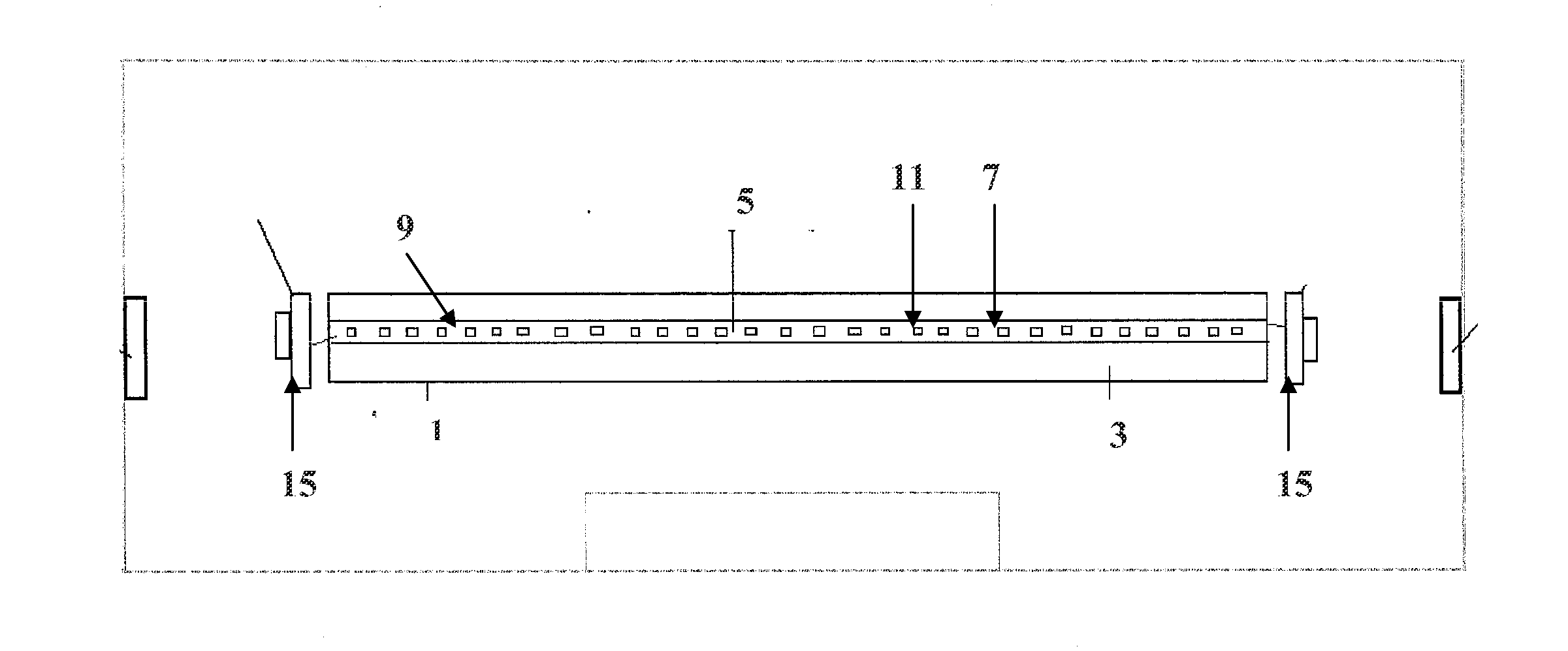
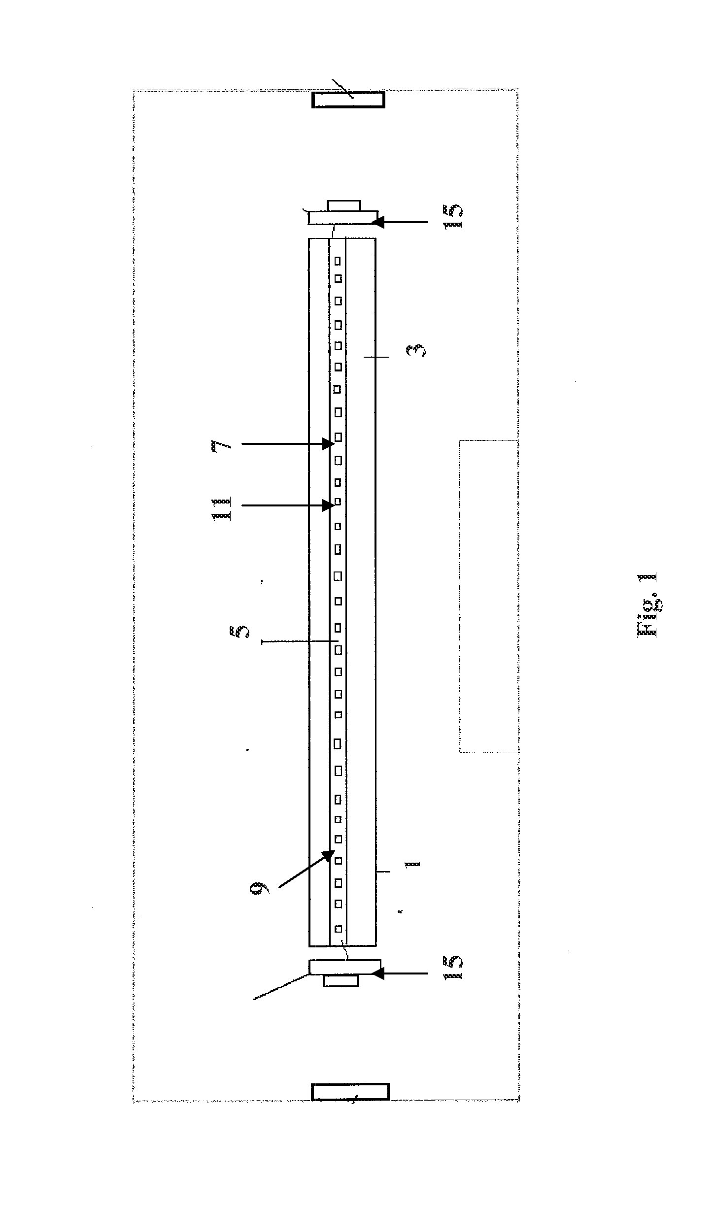
[0018]With reference to FIG. 1, one embodiment of the lighting system of the present invention comprises a hollow housing 1 having a LED divider 3 disposed therein. In some embodiments, divider 3 may be rectangular; however other shapes and configurations may be equally suitable. In some embodiments, the divider 3 is comprised of a transparent or translucent material such as polycarbonate (i.e. Lexan®), or another suitable plastic or synthetic material. The housing materially may be made of a flexible and inexpensive material as desired. The use of a transparent or translucent divider 3 provides substantial advantages over the prior art in that, where the strip is disposed on both sides thereof, the present invention provides for substantially omni-directional light emission. That being said, divider 3 may optionally be comprised of an opaque material, which provides for more directional lighting. Accordingly, divider 3 may be comprised of a metal, such as aluminum, which includes h...


PUM


Abstract

An LED lighting system comprising a housing, a divider, one or more LED strips including one or more light emitting diodes, and one or more end caps having at least one electrical terminal. The divider is disposed in the housing, the one or more LED strips is disposed on the divider; and the electrical terminal of the end caps is in electrical contact with the LED strips. In some embodiments, the end caps are adapted to engage a light socket, wherein the electrical terminal of the end caps is disposed between and in electrical contact with the LED strips and the light socket, and the light socket is in electrical contact with an electrical power source. In some embodiments, the electrical terminal defines a spring engagement between the end caps and the light socket, permitting the lighting system to rotate with respect to the light socket

Description

PRIORITY INFORMATION[0001]This application claims the benefit of U.S. Provisional Application No. 61 / 322,080, filed Apr. 8, 2010.BACKGROUND OF THE INVENTION[0002]High-output fluorescent lighting systems, commonly used in sign applications, are known to have extremely high power requirements and heat output. Such high-output systems are also not particularly reliable, nor are they environmentally friendly due to the gases that are used in fluorescent bulbs. However, light-emitting diodes (or “LEDs”) generally have lower power requirements, increased lamp life, service life, and reliability and lower overall environmental impact. Accordingly, the present invention provides an LED lighting system that is a direct replacement for high-output fluorescent lighting systems known in the art while maintaining the same high-output light emission characteristics of such systems.SUMMARY OF THE INVENTION[0003]The present invention relates generally to lighting systems and more specifically to va...

Claims


Application Information

Patent Timeline
Patent Type & Authority Applications(United States)
IPC IPC(8): F21S4/00
CPCF21K9/00F21S4/008F21V21/30F21V29/763F21Y2103/003H01R33/02F21K9/17F21Y2101/02F21S4/28F21K9/27F21K9/65F21Y2103/10F21Y2115/10F21Y2107/90
Inventor SOCARRAS, TITO
Owner SOCARRAS TITO
Learn More