Stent having a bridge structure

a bridge structure and stent technology, applied in the field of stents, can solve the problems of premature fatigue of the structural part, damage to the respective element within the bridge structure of the stent, and the increasing loss of the supporting force of the stent, so as to achieve the effect of greater volume taken up by plastic deformation energy

Active Publication Date: 2011-10-13
ADMEDES SCHUESSLER GMBH
View PDF10 Cites 2 Cited by
  • Summary
  • Abstract
  • Description
  • Claims
  • Application Information

AI Technical Summary

Benefits of technology

[0017]Moreover, according to a preferred embodiment, the at least one bridge near the node region is designed along its length with substantially identical cross-sectional areas transverse to its main line. In this context, the main line is that (imaginary) line along which the bridge in question extends. This line is in particular curved when the bridge itself is curved or bent. Since, according to the invention, the cross-sectional area of the bridge transverses this main line, it is always comparatively large. Therefore, weakening caused by tapers, as can occur in the prior art, is substantially avoided.
[0018]Particularly, viewed in the jacket surface of the stent, the width of the at least one bridge according to the invention, at least near the node region, is substantially the same size along the length thereof. In this way, compared to a tapered bridge, the volume taken up by plastic deformation energy is greater. In this way, the primary stress remaining after the plastic deformation is smaller, since the same amount of energy is distributed across a greater volume. The alternating load that can be taken up is greater by this amount.

Problems solved by technology

In known stents, although it is likewise possible in principle to select a relatively large ratio of size between the nonexpanded state and the expanded state, the stents, however, increasingly lose their supporting force, or so-called radial force, in the expanded state.
If the stresses exceed given material limits, which can generally be elongation at break and stress at break, this leads to damage of the respective element within the bridge structure of the stent.
In addition, the deformed element is subject, during use, to an alternating permanent load, which, if the maximum specific to the material is exceeded, causes premature fatigue of the structural part.

Method used


Image

  • Stent having a bridge structure
  • Stent having a bridge structure
  • Stent having a bridge structure

Examples


Embodiment Construction

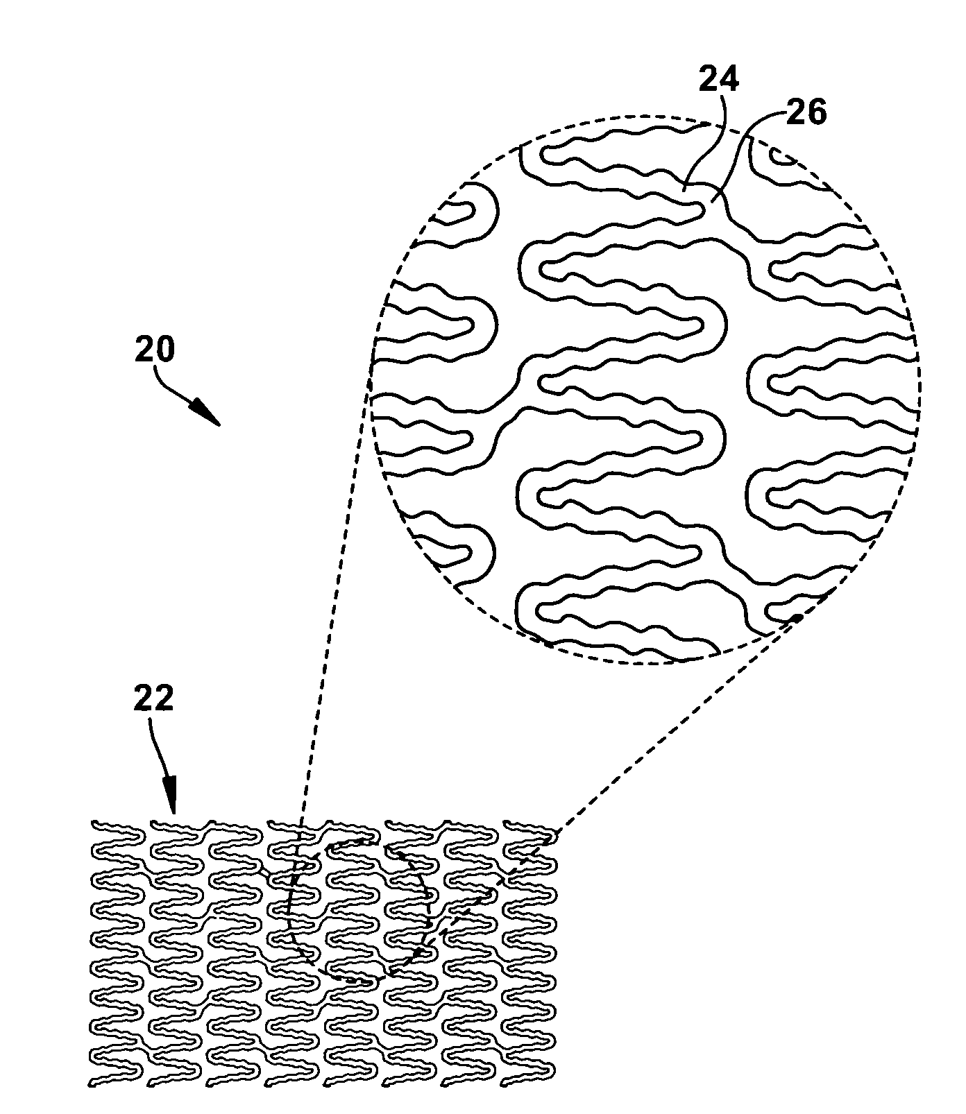
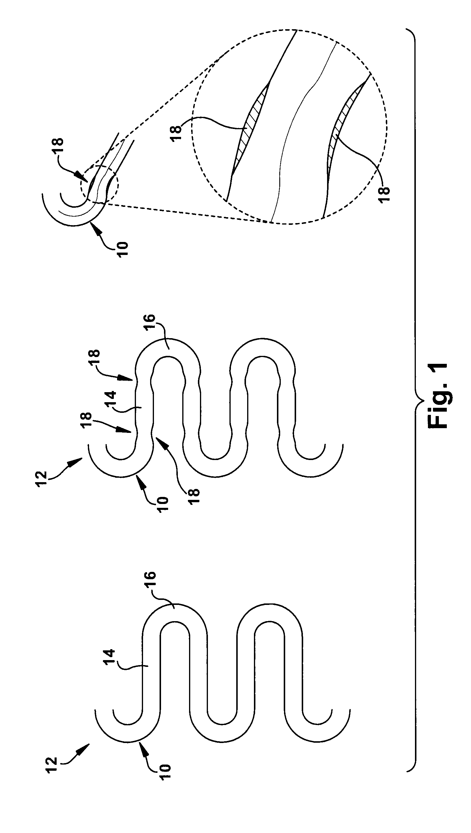
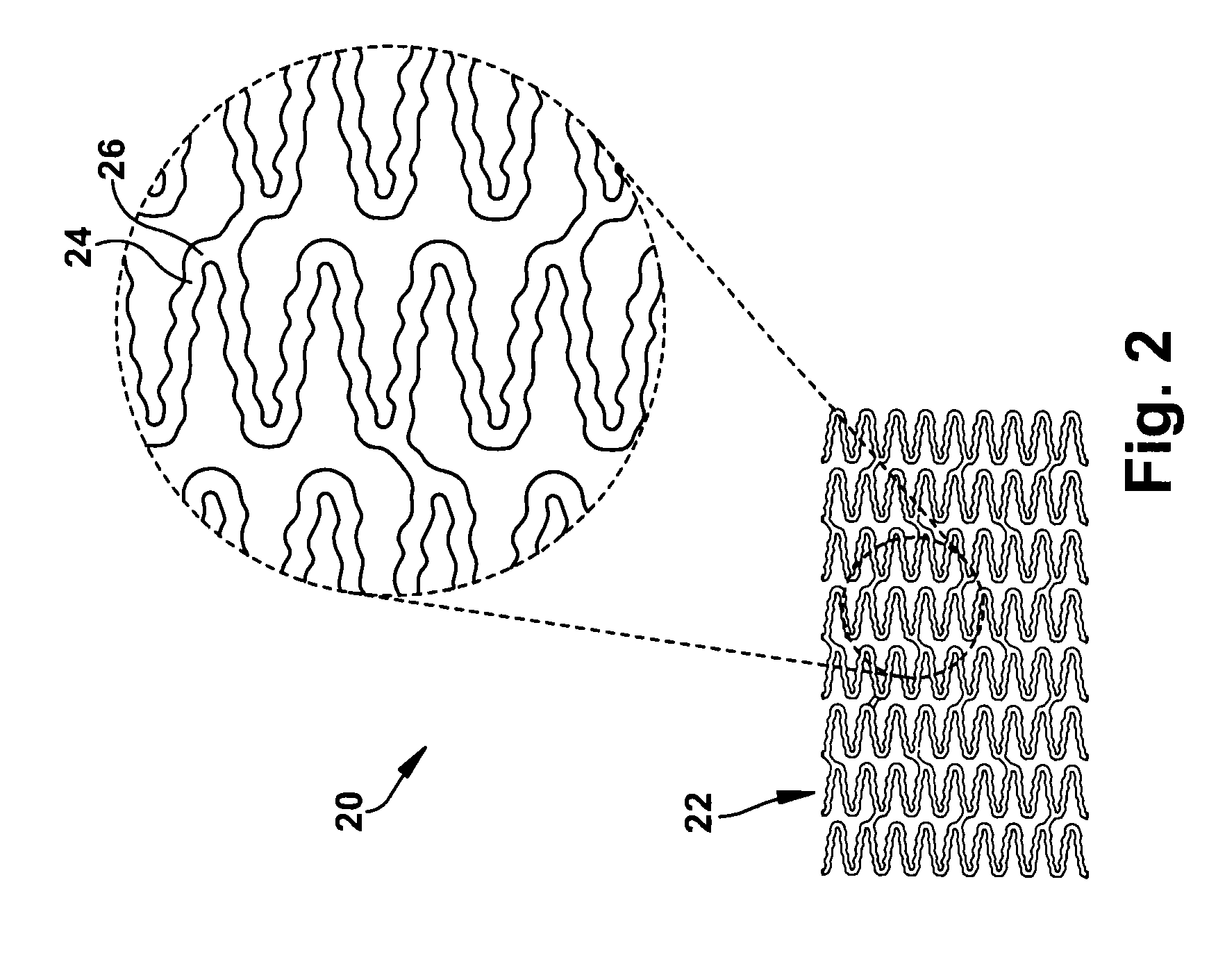
[0034]In contrast to FIG. 1 already discussed above, FIG. 2 shows a stent 20 according to an embodiment of the present invention with a bridge structure 22 in which bridges 24 are coupled to one another at node regions 26.

[0035]The bridges 24 are designed with an undulated shape along at least a portion of their length extending between two node regions 26, said undulated shape having been formed from a process such as cutting it out by a laser cutting process from a thin-walled material of a jacket surface of the stent 20. The undulated shape is designed with a number of bulges as a sequence of concave and convex arches or alternating radius elements. In the illustrative embodiment shown, such concave and convex arches are formed in succession on a single bridge 24. There can be between 3 and 12 such concave and convex arches, and in particular between 5 and 10 arches.

[0036]The undulated shape of the bridges 24 can be provided in some areas of the stent 20, i.e., not all bridges 24...


PUM


Abstract

In a stent intended for implantation in a living body and having a bridge structure in which at least two bridges are coupled to one another at at least one node region on at least one of the bridges near the node region, the section modulus of the bridge varies along the length thereof, and the stresses arising at the node region upon deformation of the stent are distributed in the longitudinal direction of the bridge.

Description

CROSS-REFERENCE TO RELATED APPLICATIONS[0001]This application is a continuation-in-part of U.S. patent application Ser. No. 11 / 081,852 filed on Mar. 16, 2005, which claims priority from German Patent Application No. 10 2004 012 837.5-43 filed on Mar. 16, 2004, each of which is hereby incorporated by reference.FIELD OF INVENTION[0002]The present invention relates generally to stents intended for implantation in a living body, and in particular, to an intraluminal stent, and having a bridge structure in which at least two bridges are coupled to one another at least one node region. The present invention also relates generally to a method for producing such a stent.BACKGROUND[0003]Stents of this kind are used to protect against collapse or occlusion of channels in living bodies, for example blood vessels, esophagus, urethra or renal ducts, by expansion of their tubular bridge structure inside the channel. They also serve as carriers for medicaments in channels of the body and thus perm...

Claims


Application Information

Patent Timeline
Patent Type & Authority Applications(United States)
IPC IPC(8): A61F2/82
CPCA61F2/91A61F2002/91533A61F2/915
Inventor EHRLINSPIEL, MICHAELFLAXMEIER, ERIKLANGE, ALEXANDER
Owner ADMEDES SCHUESSLER GMBH
Why Eureka
Try Eureka