
Modular flooring system

a flooring system and module technology, applied in the field of modules, can solve the problems of damage to the surface on which it is assembled, significant problems with respect to the maintenance of the floor, and the safety of users, and achieve the effect of providing strength and durability

Active Publication Date: 2011-10-20
SIGNATURE SYST GRP LLC
View PDF9 Cites 24 Cited by
  • Summary
  • Abstract
  • Description
  • Claims
  • Application Information

AI Technical Summary

Benefits of technology

[0010]A modular flooring system is disclosed which is designed to support heavy loads while providing stability and ground protection. The system contains an integrated connection system which is self-aligning and provides strength and durability. The system also provides increased protection of the covered ground surface.
[0011]In one embodiment, the invention contemplates a modular tile with increased strength and stability. The tile utilizes fully integrated connector loops and receiver pins located on adjacent edges. The loops and pins contain male and female edges which mate by snapping or sliding together. This system allows for self alignment of the flooring tiles. In addition, the tiles contain optional removable metal cam locks which are utilized for greater weight-baring loads. One or more metal cam locks may be located in the corners of the floor tile or along the underlay edge. The floor tiles utilize an optional base cover for additional support and ground protection. The base cover is preferably constructed from the same material as the tile. In an additional embodiment, the tiles may utilize feet with circular bases located on and extending from the bottom surface. The feet and circular base are constructed with rounded edges to prevent shearing or other damage to grass or turf surfaces.
[0012]The tiles of the present invention provide for increased protection of the covered subsurface. Specifically, the tiles contain an overlap edge, which engages with an underlay edge on an adjacent tile. This arrangement allows the tiles to overlap at an angle other than 90 degrees, providing greater strength at the point where adjacent tiles meet. The overlapping tiles help to prevent the leakage of unwanted liquids onto the ground below the tiles. In addition, the underlay edge contains a liquid capture channel which traps liquids which may seep between adjacent tiles. The tiles may be further provided with longitudinal recesses which extend through the top and bottom surfaces to the surface below. These recesses allow ventilation that is critical for grass and turf surfaces. The edges of the longitudinal recess are raised slightly above the upper surface of the tile, preventing liquids from leaking through the tile onto the surface below.
[0013]In an additional embodiment, the invention contemplates a modular floor covering system with increased strength and stability. The system utilizes a plurality of tiles with fully integrated connector loops and receiver pins located on adjacent edges. The loops and pins contain male and female edges which mate by snapping or sliding together. This system allows for self alignment of the flooring tiles. In addition, the tiles contain optional removable metal cam locks which are utilized for greater weight-baring loads. One or more metal cam locks may be located in the corners of the floor tile or along the underlay edge. The floor tiles may utilize an optional base cover for additional support and ground protection. The base cover is constructed from the same material as the tile. In an additional embodiment, the tiles utilize feet with circular bases located on and extending from the bottom surface. The feet and base are constructed with rounded edges to prevent shearing or other damage to grass or turf surfaces.
[0014]The system of the present invention utilizes a plurality of interconnected floor tiles which allow for increased protection of the covered subsurface. Specifically, the tiles contain an overlap edge, which engages with an underlay edge on an adjacent tile. This arrangement allows the tiles to overlap at an angle other than 90 degrees, providing greater strength at the point where adjacent tiles meet. The overlapping tiles help to prevent the leakage of unwanted liquids onto the ground below the tiles. In addition, the underlay edge contains a liquid capture channel, which traps liquids which may seep between the adjacent tiles. The tiles are provided with longitudinal recesses which extend through the top and bottom surfaces to the surface below. These recesses allow ventilation that is critical for grass and turf surfaces. The edges of the longitudinal recess are raised slightly above the upper surface of the tile, preventing liquids from leaking through the tile onto the surface below.

Problems solved by technology

While the dimensional changes in each individual tile are relatively small, over a large area with hundreds, perhaps thousands, of interlocked tiles, the cumulative expansion or contraction of the entire flooring system causes significant problems with respect to maintenance of the floor, as well as the safety of the users.
In practice, this expansion of the modular flooring system causes buckling, shifting and cracking of the floor tiles, as well as providing a tripping hazard for persons walking on the floor and potentially causing dangerous conditions which could cause vehicles to be diverted from their intended course over the surface of the modular floor.
In addition, the flooring system may cause damage to the surface on which it is assembled.
For instance, even short term placement of the panels on grass or turf may harm the surface due to decreased exposure to sunlight and ventilation.
Human or industrial use of the temporary flooring may also expose the underlying surface to various substances which may be harmful, for instance gas or oil that leaks from heavy equipment or food and beverages that are spilled on the top of the flooring.
As a result, damage to one of the connectors necessitates that replacement of the entire panel, thus increasing the cost and time required for assembling the flooring system.

Method used


Image

  • Modular flooring system
  • Modular flooring system
  • Modular flooring system

Examples


Embodiment Construction

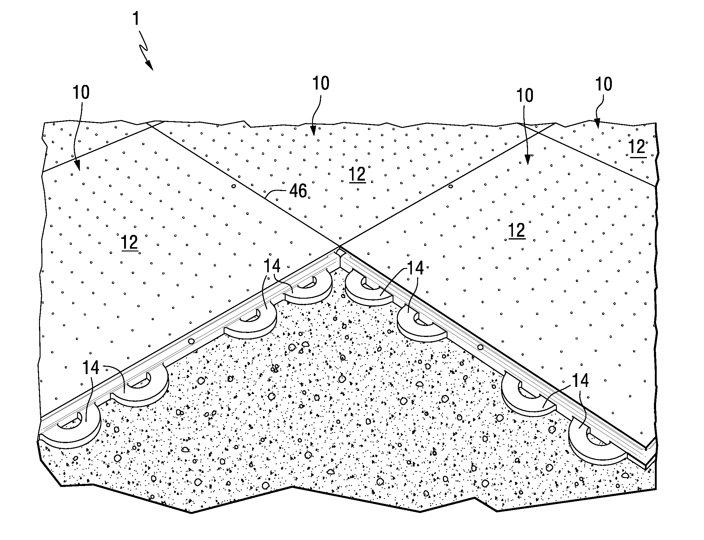
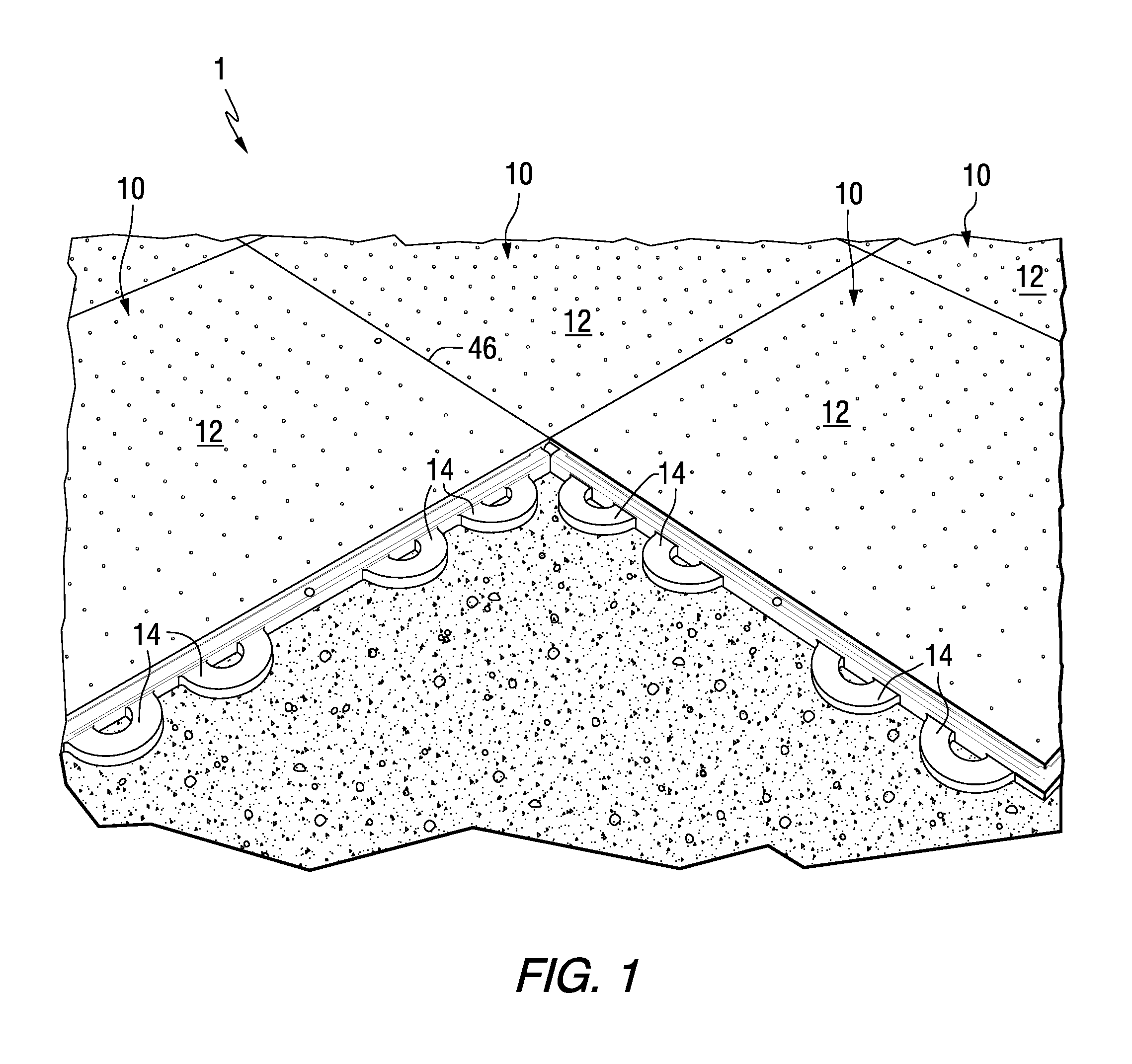
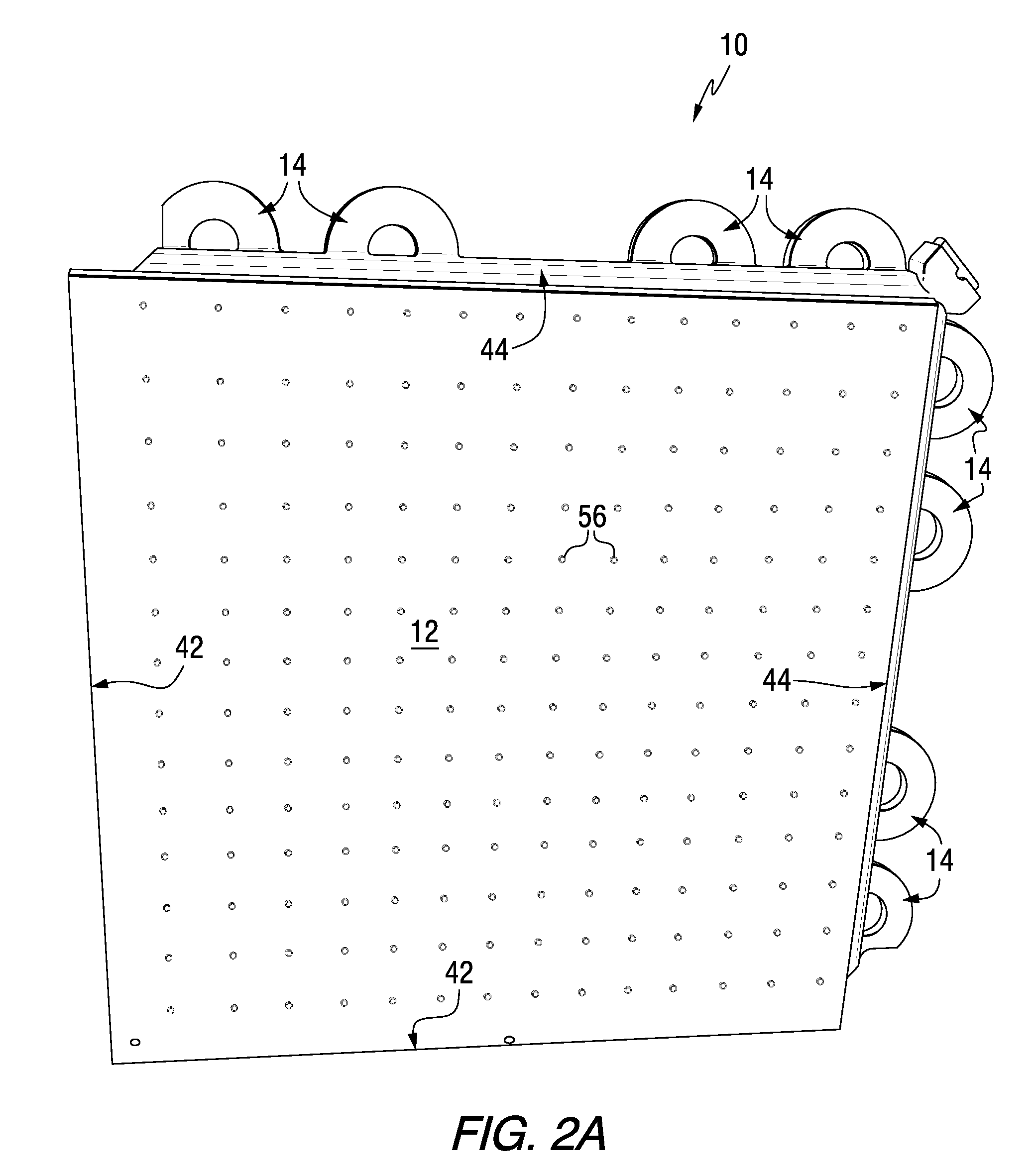
[0024]Referring to FIG. 1, a matrix of modular floor tiles 1 is illustrated having a number of component parts. Modular floor tiles 10 are provided in an interlocking matrix 1 which extends in two dimensions in accordance with a preset topographic plan. The topographic plan is typically directed towards the conveyance or support of equipment, vehicles, personnel and the like and is adapted to conform to the topographic or geographic features of the substrate surface, such as grass, dirt, artificial turf or the like. Each of the modular floor tiles 10, with the exception of the interchangeable aluminum cam locks and base cover as hereinafter described in greater detail, is preferably formed as a one-piece unit (FIGS. 2A, 2B and 2C). Each of the modular floor tiles 10 comprises a top surface 12 and a bottom surface 18. Each of the modular floor tiles 10 is generally of square configuration. However, any suitable shape, including rectangular or hexagonal, is suitable provided that the ...


PUM


Abstract

A modular flooring system is disclosed which is designed to support heavy loads while providing stability and ground protection. The invention contemplates a modular tile with fully integrated connector loops, receiver pins and optional metal cam locks located in the corners of the floor tile or along the tile edges. The tiles contain an overlap edge, which engages with an underlay edge on an adjacent tile. This arrangement allows the tiles to overlap at an angle other than 90 degrees, providing greater strength at the point where adjacent tiles meet. The underlay edge contains a liquid capture channel which traps liquids which may seep between the adjacent tiles. The tiles are also provided with longitudinal recesses which extend through the top and bottom surfaces to the surface below, allowing for ventilation that is critical for grass and turf surfaces. The modular flooring system provides increased strength and stability and protection of the subsurface.

Description

BACKGROUND OF THE INVENTION[0001]1. Field of the Invention[0002]The invention relates to a modular flooring system. More particularly, the invention relates to the use of modular floor tiles which provide increased strength, stability and protection of the subsurface.[0003]2. Description of the Prior Art[0004]Modular flooring of various designs has been utilized for a significant period of time to provide a temporary walking or other rigid surface in areas where permanent flooring is either not necessary or prohibitively expensive. More particularly, modular flooring is primarily utilized in commercial settings where a floor is temporarily needed, such as on an ice or a grass or artificial turf surface as well as in industrial or construction areas. With respect to industrial or construction areas, temporary flooring may be utilized to provide walkways, driveways, parking areas or other rigid surfaces for the transport of materials, vehicles, storage or mounting of equipment, or sim...

Claims


Application Information

Patent Timeline
IPC IPC(8): E04C2/38E04C2/40E04C2/30E04B1/70
CPCE01C9/086E01C11/225E01C2201/12E04F15/02038E04F2201/096E04F15/105E04F2201/0146E04F2201/091E04F15/02183Y02A30/30
Inventor ROSAN, ARNON
Owner SIGNATURE SYST GRP LLC
Learn More